Troubleshooting a KIT1 inverter that stayed near 90% duty cycle
After publishing the Visual Studio Code build notes for the uRADMonitor KIT1 firmware, I continued testing an inverter duty-cycle issue on my KIT1 unit.
My unit was able to reach the target Geiger tube voltage of 380V, but the inverter duty cycle was higher than expected, staying at 90%. Radu noted that the duty cycle should normally be around 40% while still reaching roughly 380V. In my initial tests, the unit was reaching the voltage target, but it was doing so while staying at that 90% duty cycle (and never going down.)
This short entry documents what I tested and what improved the behavior. It might not help everyone, as all issues are unique, but I hope it does save someone some time and frustration!
Test context
I was testing a standard KIT1 unit (1.2.107 PCB version), using a SBM20 tube. The original firmware was built from the code/124 directory of the uRADMonitor KIT1 repository. I’m assuming that you’ve already built your software and gotten the initial unit up and running – if not, please see my previous entry on how to use VSCode to compile from source, or use Wolferl’s instructions how to compile the software.
To start, we are going to change the inverter frequency in decrements of 1000 to see what that does to our duty cycle. To test Radu’s suggestion, we will recompile the code with the new frequency, reflash the 328P, and examine the unit’s webpage to determine the new duty cycle.
The inverter frequency we are interested in is located in this file in the repo:
The relevant define is:
Initial frequency testing
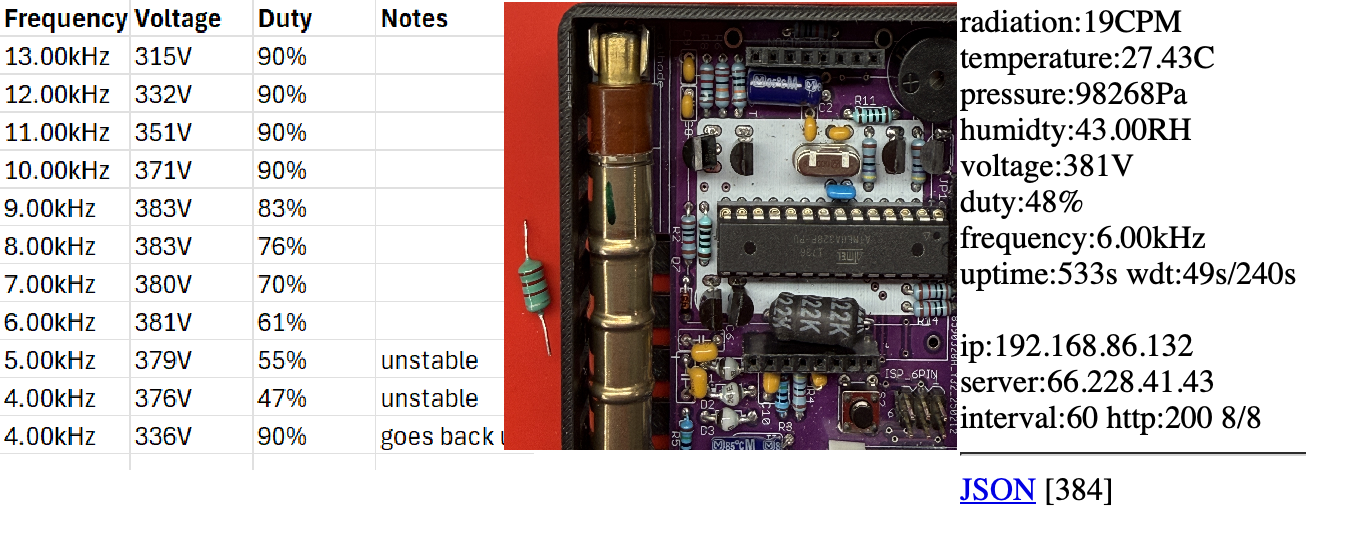
This took quite a while to recompile, program, and test, but I kept track of the duty cycles after letting the unit settle down each time I reduced the kHz by 1000. With the original inverter component (that lovely looking green inductor in the header picture next to the KIT1), the duty cycle stayed high at the upper frequencies.
| Frequency | Voltage | Duty | Notes |
|---|---|---|---|
| 13.00 kHz | 315 V | 90% | |
| 12.00 kHz | 332 V | 90% | |
| 11.00 kHz | 351 V | 90% | |
| 10.00 kHz | 371 V | 90% | |
| 9.00 kHz | 383 V | 83% | |
| 8.00 kHz | 383 V | 76% | |
| 7.00 kHz | 380 V | 70% | |
| 6.00 kHz | 381 V | 61% | |
| 5.00 kHz | 379 V | 55% | unstable |
| 4.00 kHz | 376 V | 47% | unstable |
| 4.00 kHz | 336 V | 90% | duty went back up after running |
At 7 kHz and above, the duty cycle remained 70% or higher. At 5 kHz and below, the behavior became less predictable. The unit could initially show a lower duty cycle, but at 5 kHz and below it became unstable after running for a while. The display dimmed, voltage dropped, and the duty cycle eventually climbed back toward 90%.
So, to summarize, with a questionable inductor, simply lowering the firmware inverter frequency helped somewhat, but it did not fully solve the issue on my specific unit.
Hardware change: inductor replacement
Radu suggested trying a different batch of MPSA transistors and different 2.2 mH inductors. He also suggested trying 1 mH if available. So, I went to Mouser and purchased quite an assortment of inductors and MPSA transistors. The forums here said that the most common issue was the inductor, so I started with replacing that. It was a great guess, because major improvement came after replacing the inductor with a heavier-duty 2.2 mH part! We went from a little green inductor which resembles a resistor to this big massive inductor.
The two 2.2 mH inductor types I tested were:
Datasheets:
https://www.mouser.com/datasheet/3/184/1/AIAP_02.pdf
https://www.mouser.com/datasheet/3/40/1/5800_series.pdf
After installing the new 2.2 mH inductor, the KIT1 inverter behavior improved significantly. The unit was able to reach the target voltage with a much lower duty cycle.
A typical internal web page reading after the inductor change looked like this:
....
temperature:27.43C
pressure:98268Pa
humidty:43.00RH
voltage:381V
duty:48%
frequency:6.00kHz
uptime:533s wdt:49s/240s
This was much closer to the expected behavior: around 380 V with a duty cycle near the 40% range instead of staying near 70-90% like it was before.
Why this helped (how Radu explained it to me)
The firmware logic increases duty cycle when it needs more voltage. That makes sense, but once duty cycle gets very high, especially near 90%, the inverter may not gain much useful output from pushing harder.
A weak, undersized, damaged, or poorly matched inductor can make the inverter less efficient. In that condition, the firmware may keep increasing the duty cycle to compensate, but the hardware still cannot efficiently produce the expected high voltage.
Replacing the inductor with a better-suited (heavy duty) 2.2 mH part improved the energy transfer in the inverter circuit on this unit. That allowed the voltage to reach the target range with less duty cycle.
This suggests that if a KIT1 unit is having trouble reaching the proper tube voltage, up to about 380 V, while also showing an unusually high duty cycle, the inductor is worth checking or replacing. This is especially true if reducing the inverter frequency in firmware does not bring the duty cycle down reliably. In my case, the next troubleshooting step if this didn’t work would have been trying the 1 mH inductor per Radu, then testing different MPSA42 transistor brands or batches.
Flashing caution for the 328P during repeated firmware tests
When testing inverter-frequency builds, I reflashed the ATmega328P many times. For this kind of testing, the goal is to replace only the program flash with the newly compiled uRADMonitor.hex file.
For anyone less familiar with the ATmega328P, there are three important programmable areas to keep in mind on the chip:
After your KIT1 is initially running and has received its device ID, you generally do not want to overwrite the EEPROM during normal firmware testing. (Or, you will see multiple device IDs on the map for your location if you are registered with the directory!) Also, once you initially program the chip, you also should not need to touch the fuses for these inverter-frequency tests unless you changed them for another use case.
If your programming software has checkboxes or memory-area options, make sure EEPROM and fuses are not selected. For these test builds, you should only be changing the Flash/program memory.
The test cycle should be:
1. Erase/program the ATmega328P flash memory only
2. Write the new uRADMonitor.hex file
3. Leave EEPROM unchanged
4. Leave fuse settings unchanged
This matters because the device identity or configuration is stored separately from the firmware program, while fuse settings control low-level hardware behavior such as the clock source. Accidentally rewriting EEPROM or fuses while testing firmware builds can create extra problems that are unrelated to the inverter-frequency change.
Notes and cautions
This was a practical repair/test result from my KIT1 unit, and everyone’s issues are slightly different. Mine happened to be with my inverter circuit because of the inductor, but YMMV.
The firmware frequency change was still useful for testing. Always remember to decrement it starting at the starting value of 13000 by 1000 each time (12000, 11000, etc.) A good idea and best practice is to make a backup of this file before you modify it:
My 6.00kHz frequency example:
The frequency changes worked, but in my case, the larger improvement came from the inductor replacement rather than only changing the frequency.
When testing, monitor the unit over time. A reading that looks good for the first minute may not remain stable. In my early testing, some lower-frequency settings initially looked promising, but later became unstable and the duty cycle climbed back up after a few minutes. Three to five minutes should be a good benchmark.
Another thing you can do is check whether the inverter components stay cool or only slightly warm. If components become hot, stop testing and inspect the hardware.
Summary:
This changes above brought my unit much closer to the expected duty cycle behavior of the KIT1 inverter and may save other builders time when troubleshooting a high-duty-cycle inverter condition. It also has other ideas that can continue the troubleshooting if needed (1mH heavy duty inductor in the same families such as above, or different brands of the MPSA42 transistors.)
Thank you again to Radu for responding to my e-mails and allowing me to write this article. I congratulate you celebrating over a decade since your first environmental monitoring device, and I wish you many more successful years in the future!

codemore code
~~~~