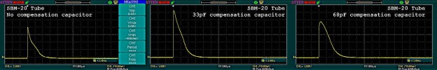
Normally, the Geiger tube delivers a sharp short pulse, with an abrupt descending path, as the quenching gas very quickly neutralises the conductive ions, and so terminating the current flow. The uRADMonitor pulses appear with a slightly rounded tip because an extra capacitor is added in the circuit, named the “compensation capacitor”. All uRADMonitor model A units have this capacitor:

Here is the original pulse, as recorded on an uRADMonitor model A unit, with the compensation capacitor removed (left picture) and a similar pulse, with the capacitor in place (right picture):

The first pulse has an amplitude of 8.48V correctly verifying the resistive voltage formula presented previously, while the second image shows a dampened pulse with a rounded tip and a decreased amplitude that is little over 5V, as an effect of the extra capacitance. Note the voltage divs are different in the two images.
Role of the compensation capacitor
Tests have shown that detectors collecting signal from the cathode, that are not using the compensation capacitor, in some certain conditions (RF Excitation, High energetic radiation event, etc), can develop an uncontrolled oscillation in the tube circuit, resulting in a very high number of pulses being falsely registered. The excellent Centronic paper on Geiger muller tubes, explains this phenomenon and the role of the compensation capacitor in a Geiger Counter circuit (page 22):
R2 and capacitor C4
When the output signal is taken from the cathode resistor R2 in the preferred way, usually via screened cable, the signal connection to the counter (whether it is via a series capacitor or not) will inevitably make some additional capacitance appear across this resistor. (The deliberate addition of a further parallel capacitor for compensation purposes is described in the next section).
As the capacitance C4 will bypass the higher frequency components of the output pulse that would otherwise have developed a voltage across R2, the effect is to slow down the leading edge of the pulse and also to lengthen the tail slightly. Provided the value of C4 is not excessive (say, <100pF), it has little effect on the operation of the tube as a counter.Compensation
If the tube is considered as a generator, and if its shunt capacitance and source resistance are ignored, the application circuit can be redrawn as shown in Figure 17(a). We can then consider R1 and R2 together as forming a potential divider connected across the generator, and Ct to C4 must equal the division ratio of R1 and R2. We can then write the following equation:
R2 / (R1 + R2) = Ct / (Ct + C4) . So, R1 * Ct = R2 * C4 (or C4 = Ct * R1 / R2 ).
The stray capacitances C2 and C3 shows in Figure 14 have been lumped together. This is permissible because, for the pulse generated by the tube, the supply rail and ground are at the same AC potential.
Some practical values that are typical for the ZP1300 tube, R1 = 2.2 MO, R2 = 47ki2, and (C2+C3) = 2pF. With these values, a value of 90p F for capacitor C4 will give appropriate compensation.

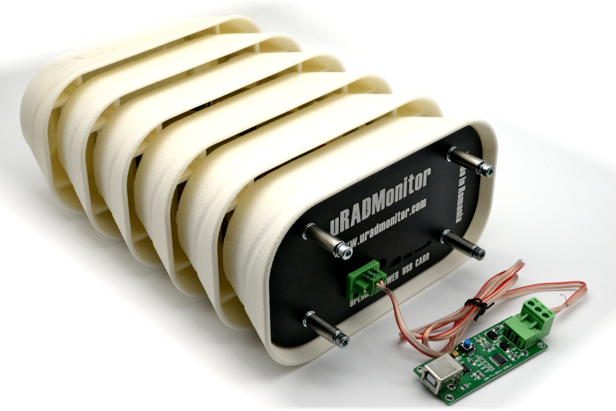
The uRADMonitor model A units use the SBM-20 and SI-29BG tubes. The R1 = 10MO and R2 = 220KO . The SBM-20 has a capacitance of 8pF and the SI-29BG, thanks to its large anode, has a higher capacitance of 12pF, despite the smaller size.
As the formula presented in the Centronic paper would give C4 = 8pF * 10MO / 220KO = 363pF for the SBM-20 and C4 = 12pF * 10MO / 220KO = 545pF for the SI-29BG, values that are too big, a more convenient value of 68pF has been selected for the compensation capacitor, that functions with good results, without affecting the pulse shape and width too much.
Geiger Pulse oscillographs


a very important concept. I face false pulse issues with highly sensitive LND7807 GM tube with 150cps/mR/hr sensitivity. This concept solved it. I also studied the centronics paper in details after that.
happy to hear that! Post pictures with your build if you wish.
sorry for delayed reply. It was a simple design.
i was using LND7807 high sensitivity gm tube. with 150 cps/mR/hr pulse rate.
At high count rate yere was uncontrolled oscillations.
Tube Capacitance is 8pF
R-Anode is 3.3M
R-Cathode is 330k
by calculation I got nearest value of 82pF.
The oscillations and false counts disappeared and I got a proper linear output for a good range of 0 to 100mR/hr without problems.