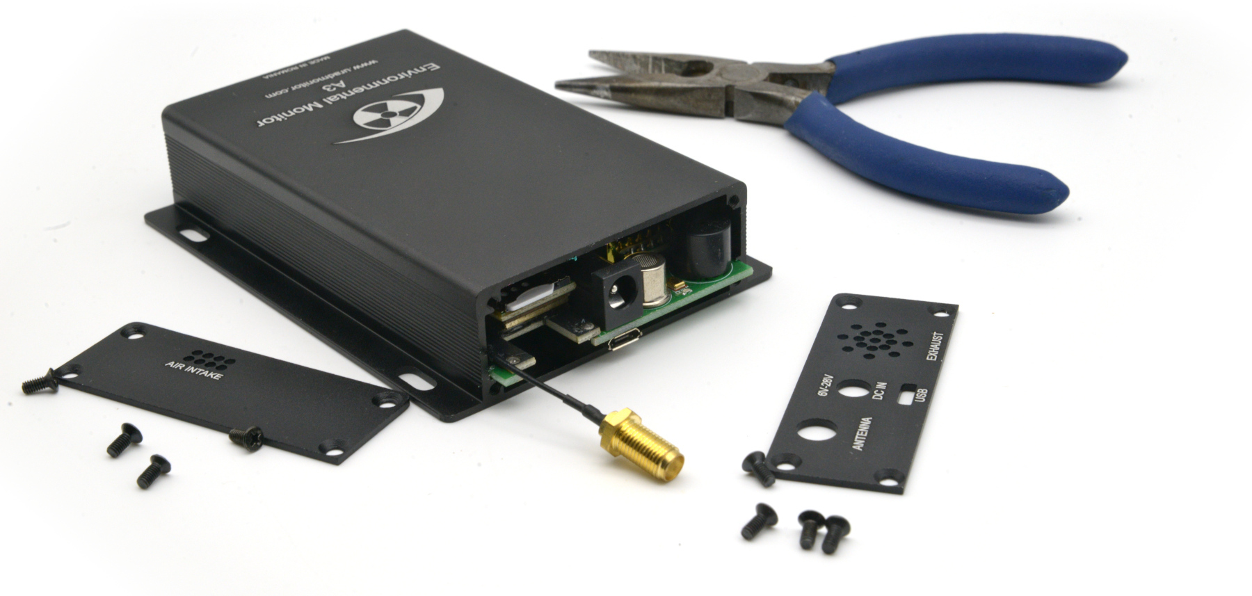
The Geiger tubes used in uRADMonitor model A units are mostly the SBM-20 or the SI-29BG, both of Russian provenience, manufactured at military grade specs. Therefore they were meant to resist fluctuations over a wide interval of temperature or pressure. If a tube failure is suspected for a particular uRADMonitor unit, for example when the number of counts per minute reported shows zero, checking the Geiger tube might be necessary, and the following indicators should be verified:
Voltage on tube
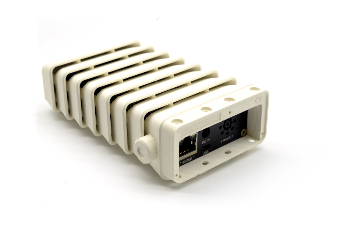
Assuming the uRADMonitor unit is otherwise functional, it should first be connected to the LAN Network to get a valid IP, so that it can be accessed locally by opening the IP in the web browser:

The voltage on tube is displayed in the web interface, together with several other parameters. The voltage on tube should read 380V +- 5V. The duty cycle must be between 25% and 48%.
This method of checking the tube voltage is preferred over directly measuring high voltage inverter output for a several reasons:
– it is safe: no electric shocks can accidentally occur by touching the high voltage sections of the circuit
– a high impedance voltmeter would otherwise be needed to directly measure the voltage on the board. A 10M impedance voltmeter (or higher) would be needed to measure the voltage directly, to avoid the voltage drop and so erroneous readings to a maximum extent. The high voltage inverter is a low current high voltage supply.
If both the “radiation” and the “average” fields show zero while the “voltage” is correctly measured close to 380V, it could indicate a tube failure. For certainty in this case, direct tube verification is needed, and the following approaches should be used:
Geiger tube pulses
The purpose of the Geiger tube is to count radiation induced pulses. When the tube internal environment is ionised by intersecting radiation, it becomes conductive for a very short amount of time. The anode (for example 10M) and cathode (for example 220K) resistors form a resistive divider. If the signal is collected from the cathode, then the maximum pulse amplitude for 380V across the entire assembly will be Vout = 8V according to the following calculations:

To test the tube is functioning properly, we need to check it is able to count radiation pulses. In the absence of an active radiation source, the background radiation can be used as a source, which for the SBM-20 should be about 20CPM (counts per minute), depending on the particular region. So a first test would be to see if the tube registers any pulses, and to count them to see if we get the expected number, that is approximatively 20 pulses in a minute. Due to the random nature of radiation, we will get more or less, but repeated tests should slowly tend to reach this value. On the other hand absolutely no pulses at all, would clearly be an indication of tube failure.
Method 1, “Poor man’s test” : use a pair of headphones to “hear” the pulses. Despite the disgraceful name, this method is actually a very quick and effective method of counting the output pulses, by making them audible in a pair of headsets:

With the headphones mounted, the jack connector needs to be caught between fingers, expect for the top contact, which needs to be put in contact with the tube’s anode (both the cathode and anode will register the pulse, but for the purpose of this test, the anode produces better audible sounds). If present, the pulses will be clearly heard with no background noise.
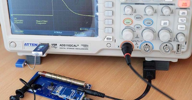
Method 2, using an oscilloscope : brings certain advantages like also seeing the pulse shape, amplitude, and the possibility of counting the events automatically. For the signal at cathode topology, we need to do the measurements across resistor R2. Connect a 10X probe like follows:

Select a voltage div of 1V and for the time div use both a long 500ms interval to see several successive pulses, but also a shorter time div of 100uS to see individual pulses. The following picture shows two representative oscillographs:

For this SBM-20U tube, the dead time is also visible and it is little over 100uS. The detailed picture shows a pulse with a rounded tip, indicating a capacitance in the circuit. Indeed, there is a so called “compensation capacitor”, responsible for this effect, explained in a separate article: The compensation capacitor. It is this capacitor that makes the pulse rounder and it also reduces the amplitude.
The absence of any such pulses would again indicate a tube failure responsible for the counter showing 0. The images above show a correctly functioning tube.
The counter
It may happen that a tube is in good state, but the counter electronic circuit is malfunctioning and the CPMs will show 0 (radiation and average readings), or the inverter fails to deliver the minimum Geiger tube voltage, and so there won’t be any counts either. While the latter can be easily verified by checking the voltage and duty cycle parameters displayed in the LAN web interface, the questions remains for the former situation.
Is it the tube that failed, or the counter circuit?
As explained previously, the Geiger tube does nothing more but to become conductive when ionised by radiation for a tiny amount of time (also called the dead time as the tube is unable to detect a simultaneous second radiation event, that happens at the same time with the first). Simulating a conductive tube is easy, by simply short-circuiting it’s connectors: using a conductor, shortly put the tube anode in contact with the cathode. If the counter circuit is functioning properly, the short-circuit will be registered as an avalanche of pulses (because of the imperfect contact of the wire quickly touching the tube’s ends). If the web interface continues to show 0, there is a hardware problem in the counter circuit and changing the tube will not help, since the tube is probably not the problem in this case.

codemore code
~~~~