Forum Replies Created
-
AuthorPosts
-
uRADMonitor
KeymasterHi Abraham, and welcome!
Indeed your readings are higher. We’ll need to expand the network in your area and have some redundancy on the measurements.
KeymasterCoordinates for your unit, 5100005D, changed as per your request. Congrats on running the first unit in Mexico!!
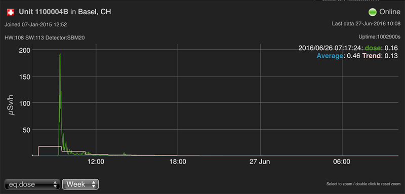
https://www.uradmonitor.com/?open=5100005DI’m surprised to see the higher readings there. I wonder what is the cause for that
-
This reply was modified 9 years, 8 months ago by
uRADMonitor.
KeymasterCoordinates changed!
KeymasterI saw it as well. Will try to get more data on it.
Attachments:
KeymasterAs soon as the security is implemented to something similar to what you have suggested (the key, etc). Currently all efforts go towards finalising the model D hardware.
KeymasterThe 2.2K couldn’t have harmed the circuit in any way.
KeymasterHi Hashy!
Don’t be too harsh on yourself.
If I got it right, what happened is that you pressed the tube against the middle clip and that punctured the tube?
The middle connector is there for those that want to use the shorter SI3BG tube, very insensitive, but better to offer it as an alternative.
The SBM20 which is supplied with the KIT, only needs the to far-end clips for support.
Now, if the tube is broken, it lost its internal gases and special pressure parameters, making it impossible to register any counts, exactly like you described. If touching the contacts results in counts, this shows your soldering skills are OK, and replacing the tube will get it working.
Sorry for this, I’ll make sure to add the SI3BG details to the next manual revision. Also, make sure the seller sends you a tested/working SBM20 tube, and not anything else (like STS-5, etc, some sellers are not serious about what they are doing).
And please post some pics, might be useful for others reading this. At least as a warning.
KeymasterAmazing work ecloud! Also thanks for the great feedback.
LE: also published on the project’s FB page: https://www.facebook.com/uRADMonitor/
-
This reply was modified 9 years, 9 months ago by
KeymasterThat looks good. Sorry for the confusion with the resistors, I’ll make sure to correct it in the next version of the PCB. As said, it was to preserve backwards compatibility for using the LM317 instead of the better LM1117 . And backwards compatibility is a pain, nearly every time.
Radu
KeymasterThat is personal information that can’t be made public by default.
KeymasterThat’s an excellent solution, Robert; the tube connectors should have been one size bigger. Will keep this in mind for the next batch, I used the correct size for my prototypes, but the factory which helped me with production, mixed up the sizes (those are 5mm fuse holders, should have been 6mm).
KeymasterI also sent you by mail versions of the firmware configured for lower inverter frequency (down to 6.5KHz). Please test them and let me know if it helps.
KeymasterHi Curt,
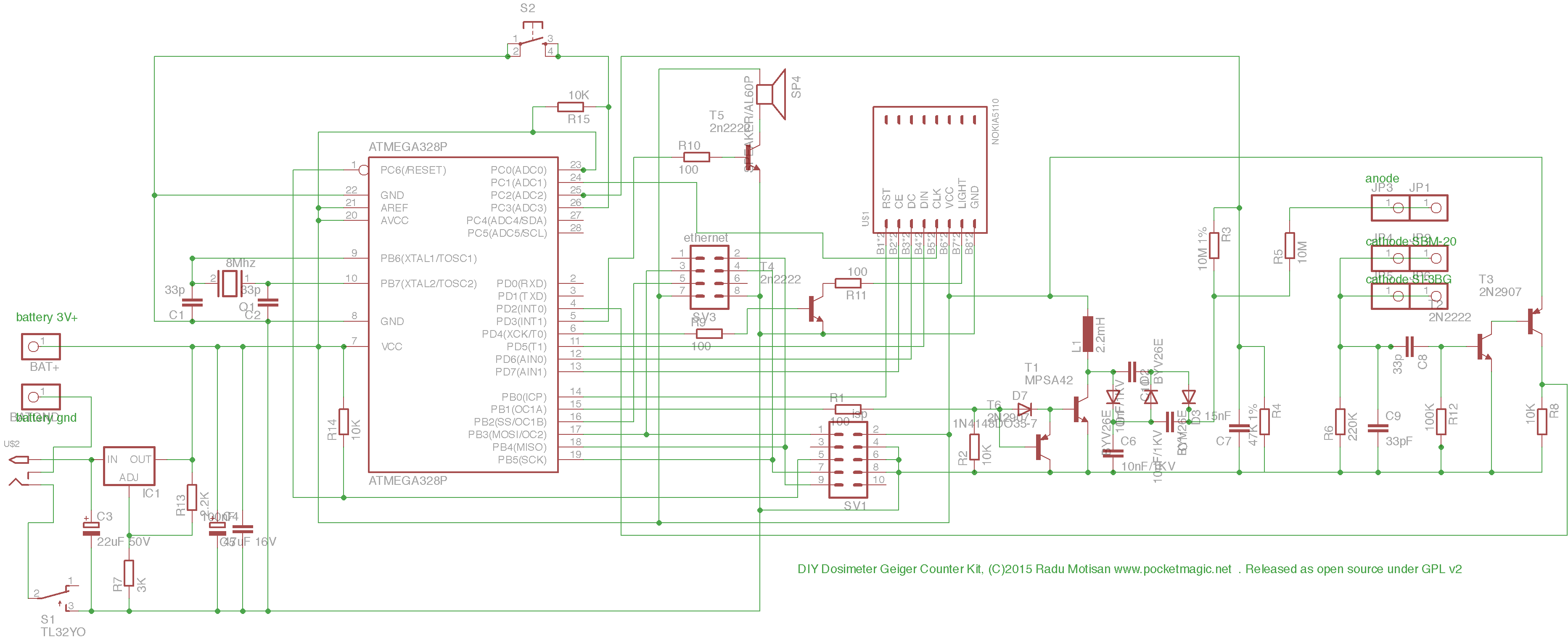
Here is the diagram of v102 : http://www.pocketmagic.net/wp-content/uploads/2015/10/uRADMonitor_KIT1.1_sch.png
The IC1 is the 1117 regulator, the ADJ pin needs to be connected to GND, that goes through R7, so make sure you replace it with a wire.
The R13 must not be connected. On the v103, the naming of R7 and R13 is reversed, wish I didn’t do that.
The idea with these resistors is that instead of the LM1117, you could use the LM317, and the resistors were chosen to give out 3V. On a next revision (104), these will be removed completely.
KeymasterI’ve seen this before, and the problem was related to the inductor. Try getting 2.2mH inductors from a different source, or ,as a quick dirty hack, put two 2.2mH inductors of the kind you have now in parallel.
We might get over this by changing the frequency the inverter operates at – drop me a mail so I can send you a test firmware that uses a lower frequency (that might get noisy).
KeymasterHey guys! Thanks for the feedback. Next edition will have better silkprint for those resistors, I’ll also take care to improve the manual’s print quality .
-
This reply was modified 9 years, 8 months ago by
-
AuthorPosts