- This topic has 87 replies, 21 voices, and was last updated 6 years, 1 month ago by
Justy89.
-
AuthorPosts
-
June 20, 2016 at 9:11 am #3061
uRADMonitor
KeymasterThat’s an excellent solution, Robert; the tube connectors should have been one size bigger. Will keep this in mind for the next batch, I used the correct size for my prototypes, but the factory which helped me with production, mixed up the sizes (those are 5mm fuse holders, should have been 6mm).
June 25, 2016 at 7:58 pm #3070ecloud
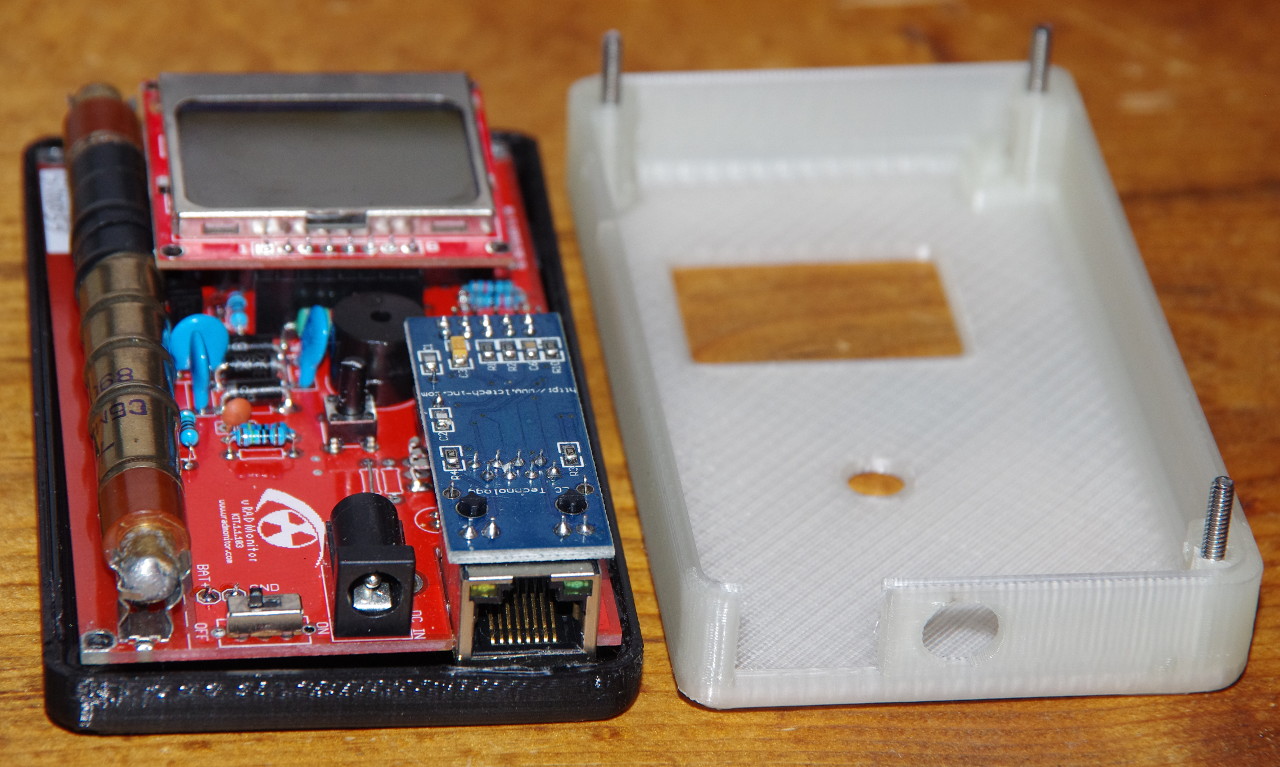
ParticipantI also managed to bend the legs of the fuseholder such that it’s possible to solder both ends, like Robert described. They strike me as quite a flimsy holder for the tube; but on the other hand, they are also too close to the mounting holes. So since they are so flimsy, it wasn’t too hard to bend them over a bit crooked, to make it possible to bolt the board into a case I designed, which is here: http://www.thingiverse.com/thing:1644939 The case includes struts which, if you have bent over the fuseholders the same way I did, will help hold the tube in position, so that it doesn’t fall out.
I’d suggest using sturdier fuseholders, but also making the board just a little bigger, to get those mounting holes away from the tube. Also, it would be nice to have holes on all 4 corners, not just 3. Moving the ethernet module over might make it possible.
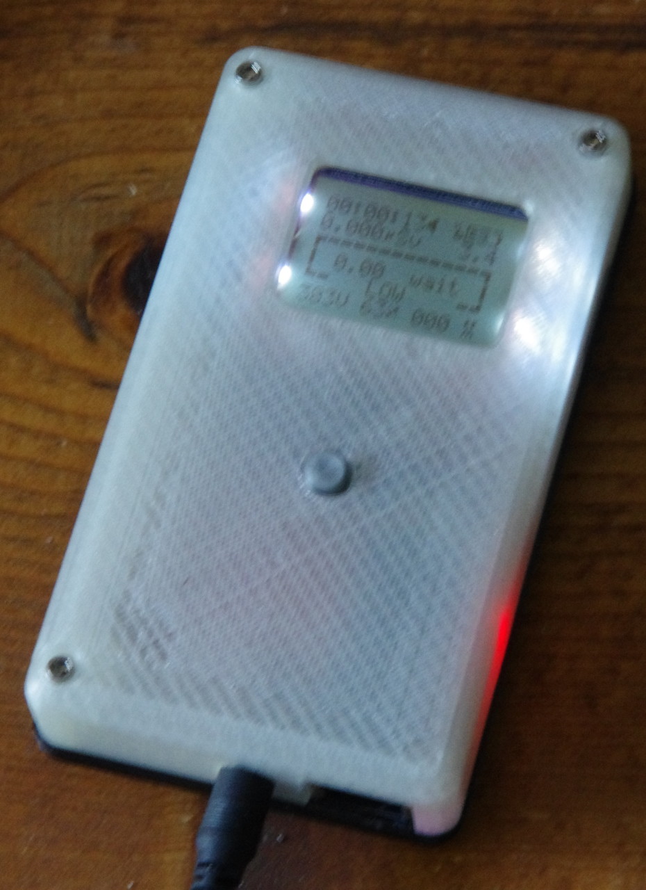
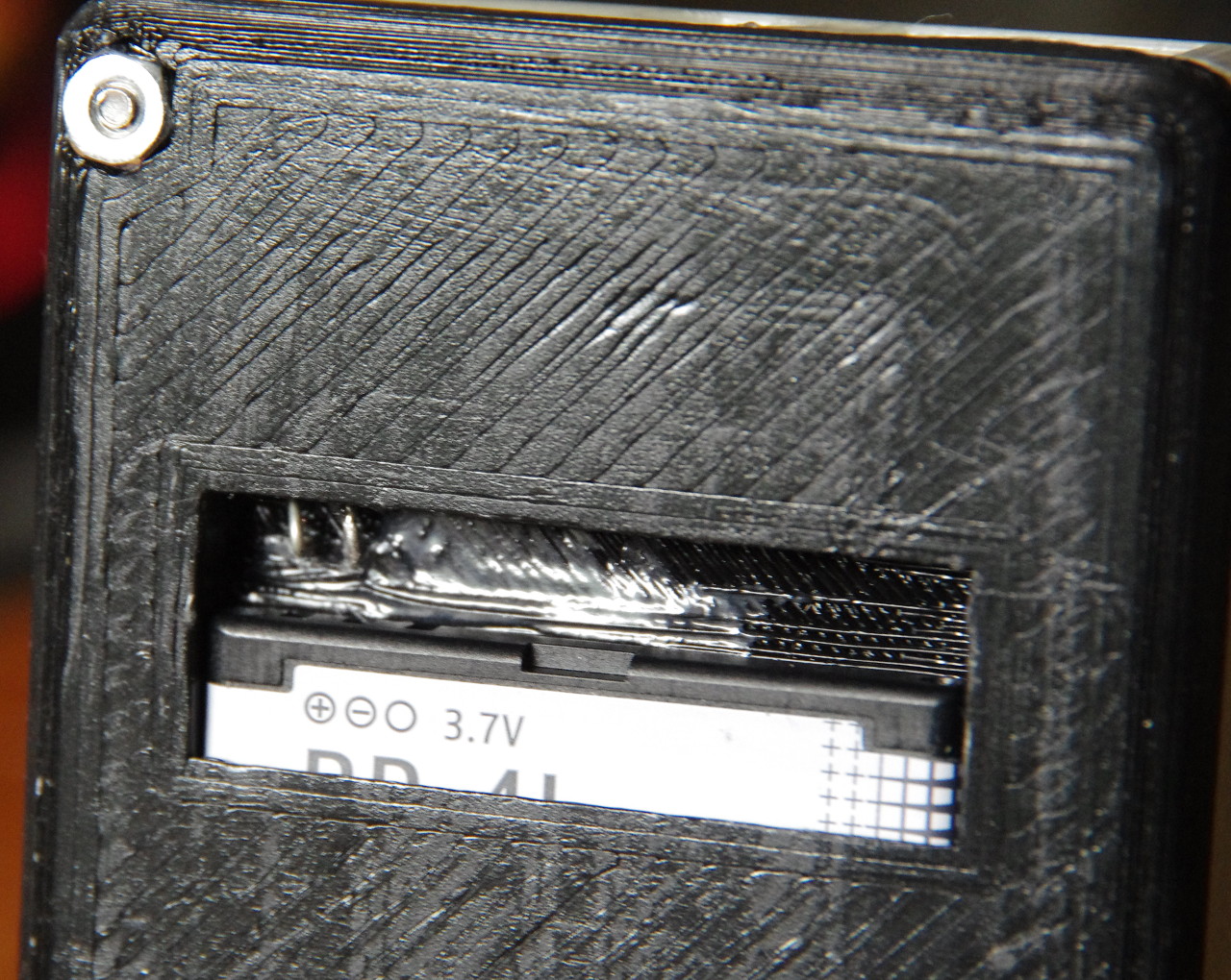
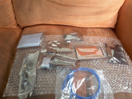
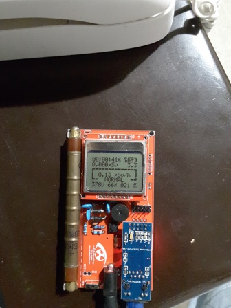
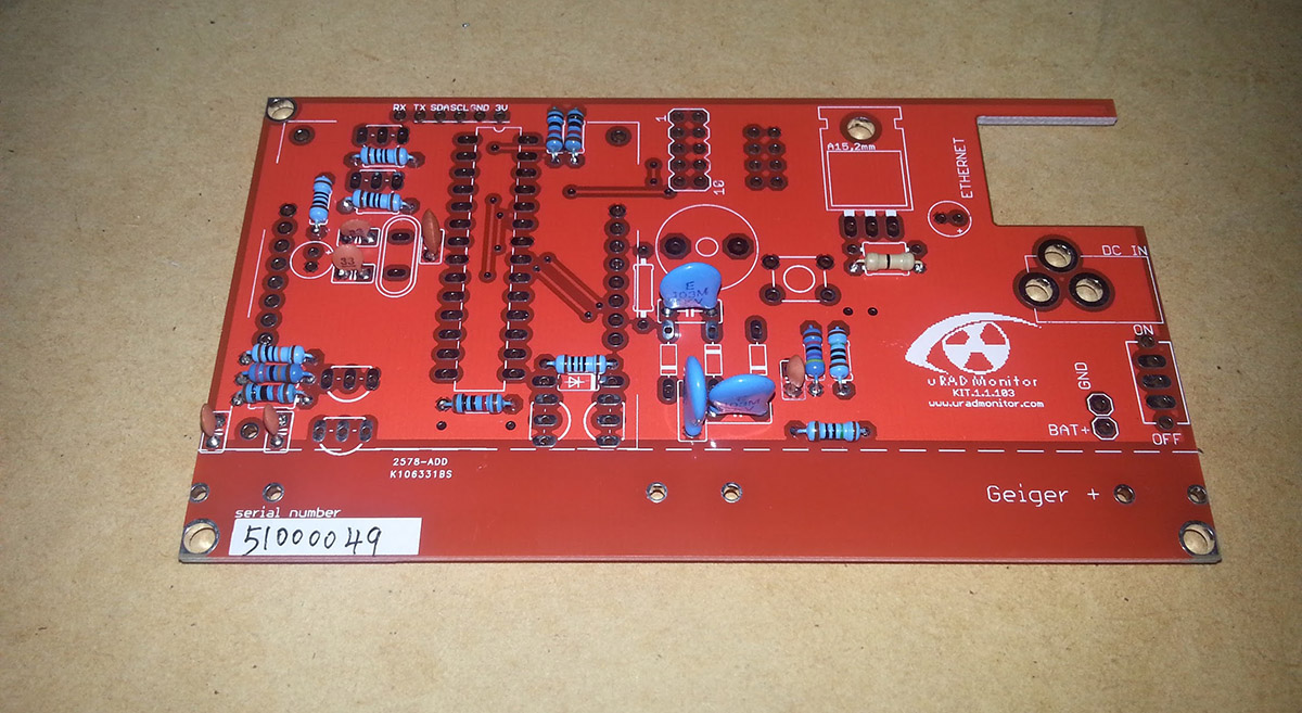
I will leave it plugged into the network at home most of the time I guess, but designed the case so that I can slip a Nokia BP-4L battery into the back, for checking other places around town, etc. 3.8V is too high, so I used a diode to drop it down around 3.2-3.3V. At least this way I didn’t need to bulk it up to make space for a pair of AA’s. But using this type of battery is fiddly. It’s nice that the battery can clamp onto the battery contacts in the phone, instead of needing spring-loaded contacts. But you need something resembling the contacts in the phone. I used diode legs as battery contacts. Maybe I should make a PCB which can hold the actual surface-mount Nokia battery contacts that can be found on ebay, and have the board double as the inside plane of the battery holder, and slot into the case somehow. It could have a battery charging controller too. For now I will need to use a separate charger.
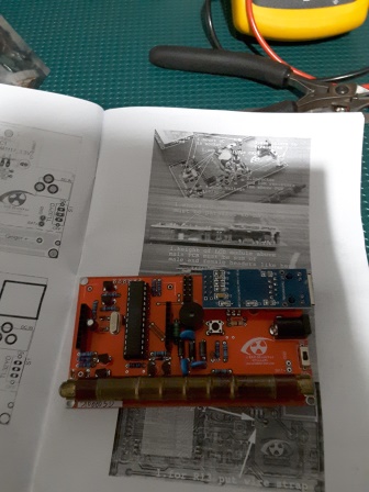
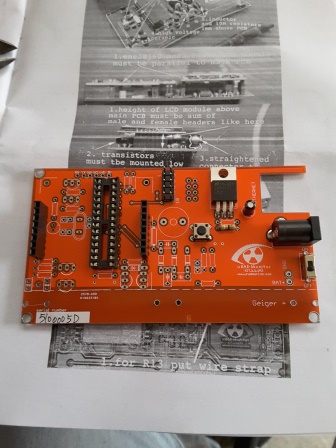
Attached pics are simply the board during assembly. Thingiverse has more pics of the case design.
June 25, 2016 at 8:13 pm #3075ParticipantHere are a couple more pics.
June 25, 2016 at 8:26 pm #3079KeymasterAmazing work ecloud! Also thanks for the great feedback.
LE: also published on the project’s FB page: https://www.facebook.com/uRADMonitor/
-
This reply was modified 10 years, 1 month ago by
uRADMonitor.
June 27, 2016 at 8:39 pm #3089Mads Barnkob
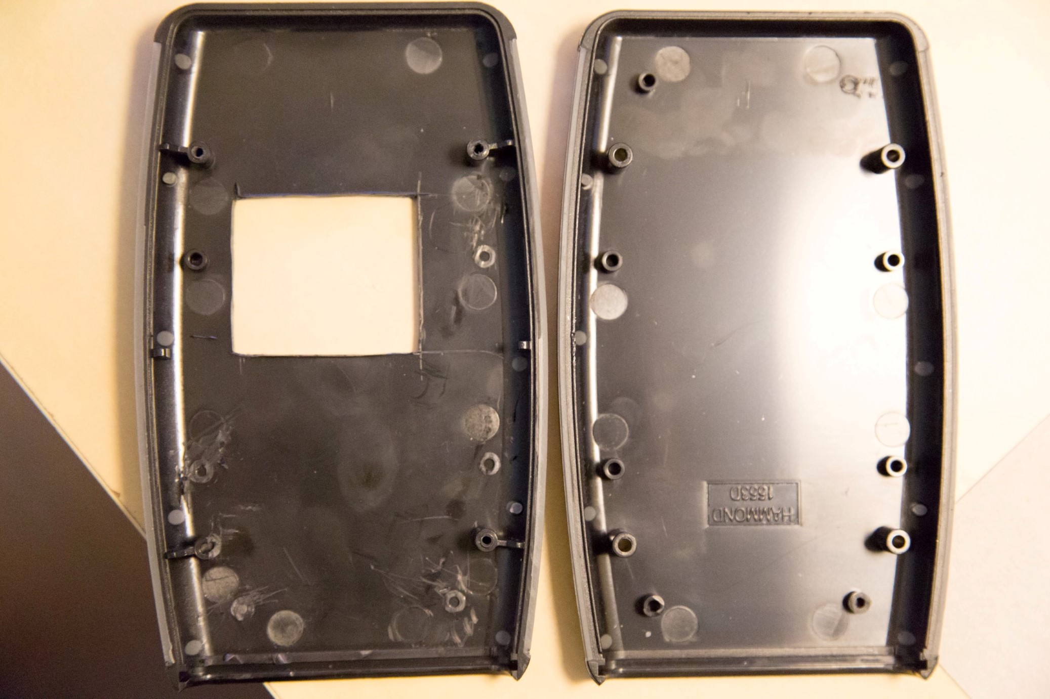
ModeratorI took a chance with a handheld project box found on ebay, which I already knew could not fit the KIT1 in its inside dimensions, so I took a shot at it and hoped I could hack my way to success 🙂
It is a Hammond 1553D Enclosure and it can be bought from many different sellers under names like “Soft sided Hand Held Enclosure Black 147 x 89 x 25 ABS Project Box Case” ( http://www.ebay.co.uk/itm/301490335412 )
I had to drill two holes in the KIT1 PCB to make it fit between the enclosure supports where the screws that holds it together is driven through. Luckily there was no tracks in the way, so no bridges had to be made.
I also had to cut down every pin on the ethernet board and screen board to get enough clearance for the lid to fit on. The ethernet connector is also soldered as good as welded on to the board 🙂
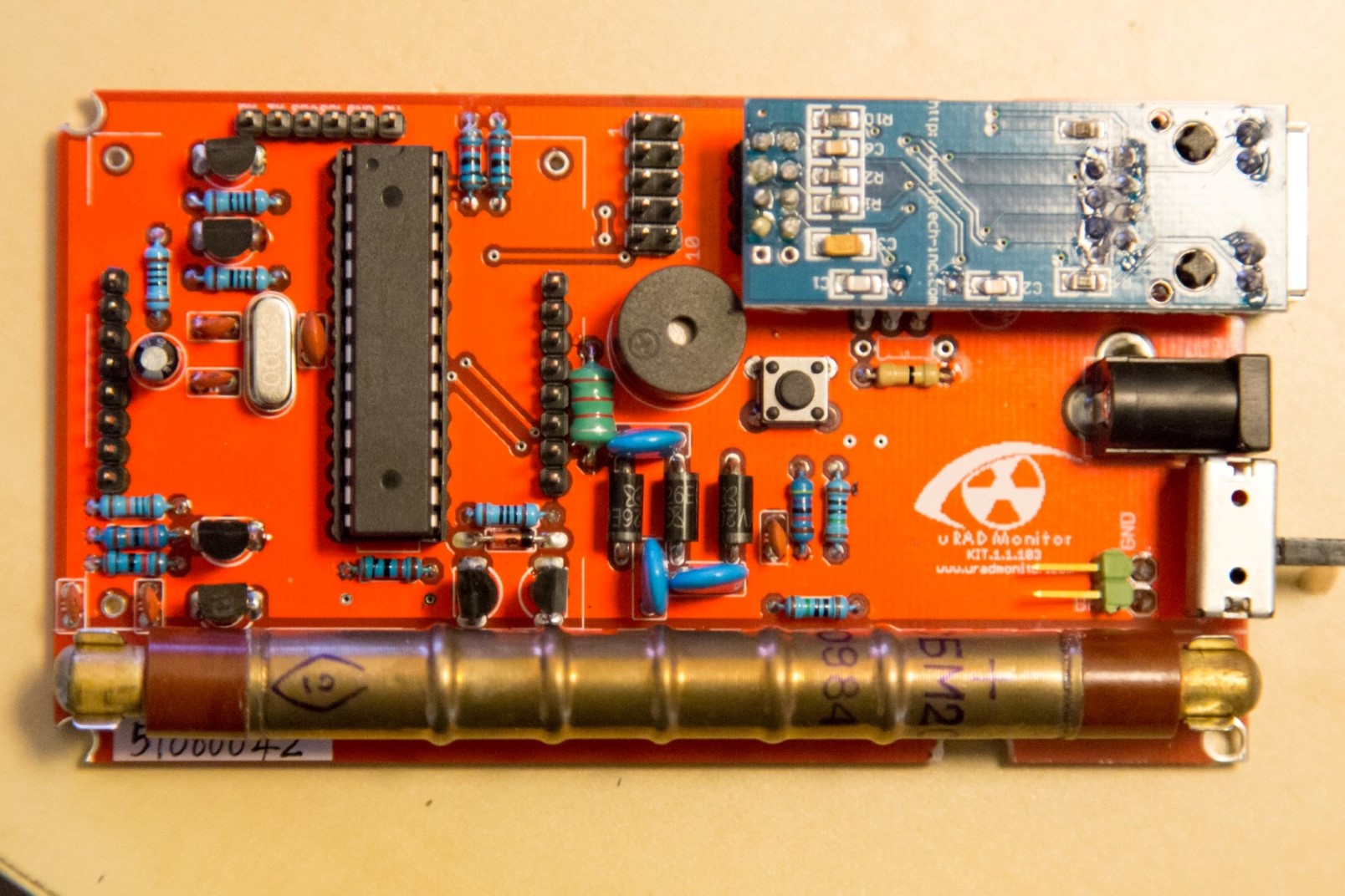
The PCB itself is perfectly soldered and with all components aligned either top to bottom or left to right, everything in same height, everything straightened to sit perfectly in its silk screen. The OCD was strong on assembling this.
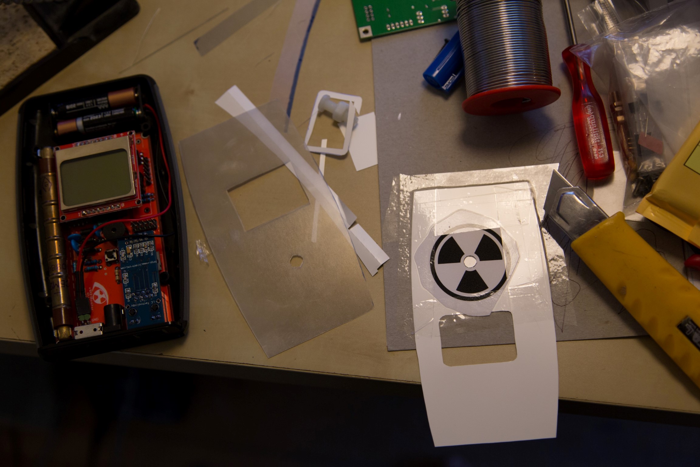
Everything in the enclosure it cut by hand, the white front cover is plastic from a LCD monitor backlight scatter layers and the push button is a M6 nylon bolt. I also changed the on/off button to a sideways so it was able to be operated from the same front as which power in and ethernet goes through.
I also added a regular 2xAAA battery holder.
Cutting the radioactive logo was enough for me, the blade dulled just from that and I gave up doing a much finer cut of “uRadMonitor” above the screen.
-
This reply was modified 10 years, 1 month ago by
Mads Barnkob.
Attachments:
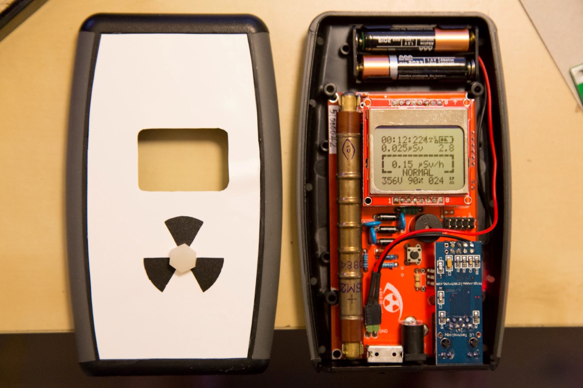
June 27, 2016 at 8:41 pm #3094ModeratorMore pictures
And if you notice a dent on the right of the white front, near the screen, well… I accidentally drop-tested it from a good 1 meter height. Still works 🙂
Attachments:
July 3, 2016 at 3:18 am #3104Jasso
ParticipantGreetings from sunny Mexico!
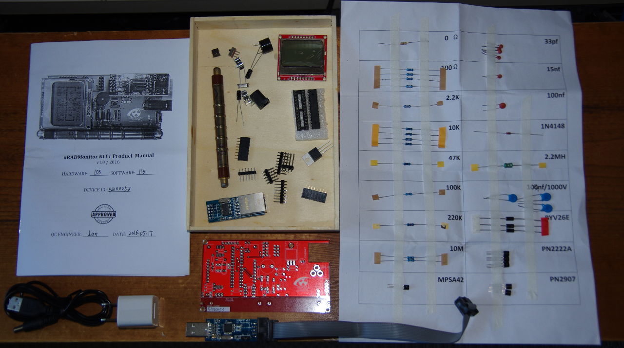
So yeah, my kit finally arrived this week, and today i got myself commited to assembling it. Note that as someone else posted, the printed manual is on the low quality side, so the chance for potential error increases if you are not fully paying attention to what you are doing. Now all that i need is a case for it! there is a good chance that i will take it offline until it has a proper enclosure, don´t want the kids playing around those high voltages! on the plus side, what an awesome little kit! (really missed the silk screened component identifiers). Any how, thank you Radu for designing such a nice toy! I have attached some pictures of my buildout, for your amusement!July 11, 2016 at 12:21 pm #3169Moran
ParticipantI have soldered mine the case is waiting for me to have time to complete some upgrades to my 3d printer
There is an issue connecting to the network it doesen’t appear to be picking up an IP address.
I logged into the router the uRadmonitor is listed in DHCP table as expired.
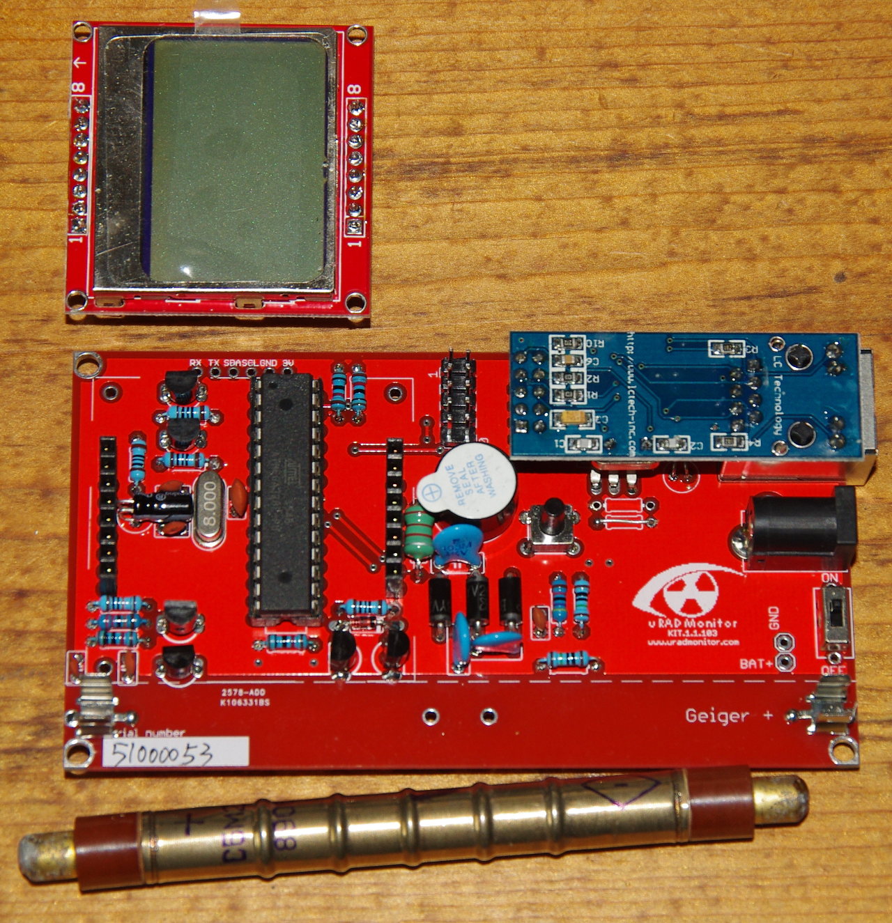
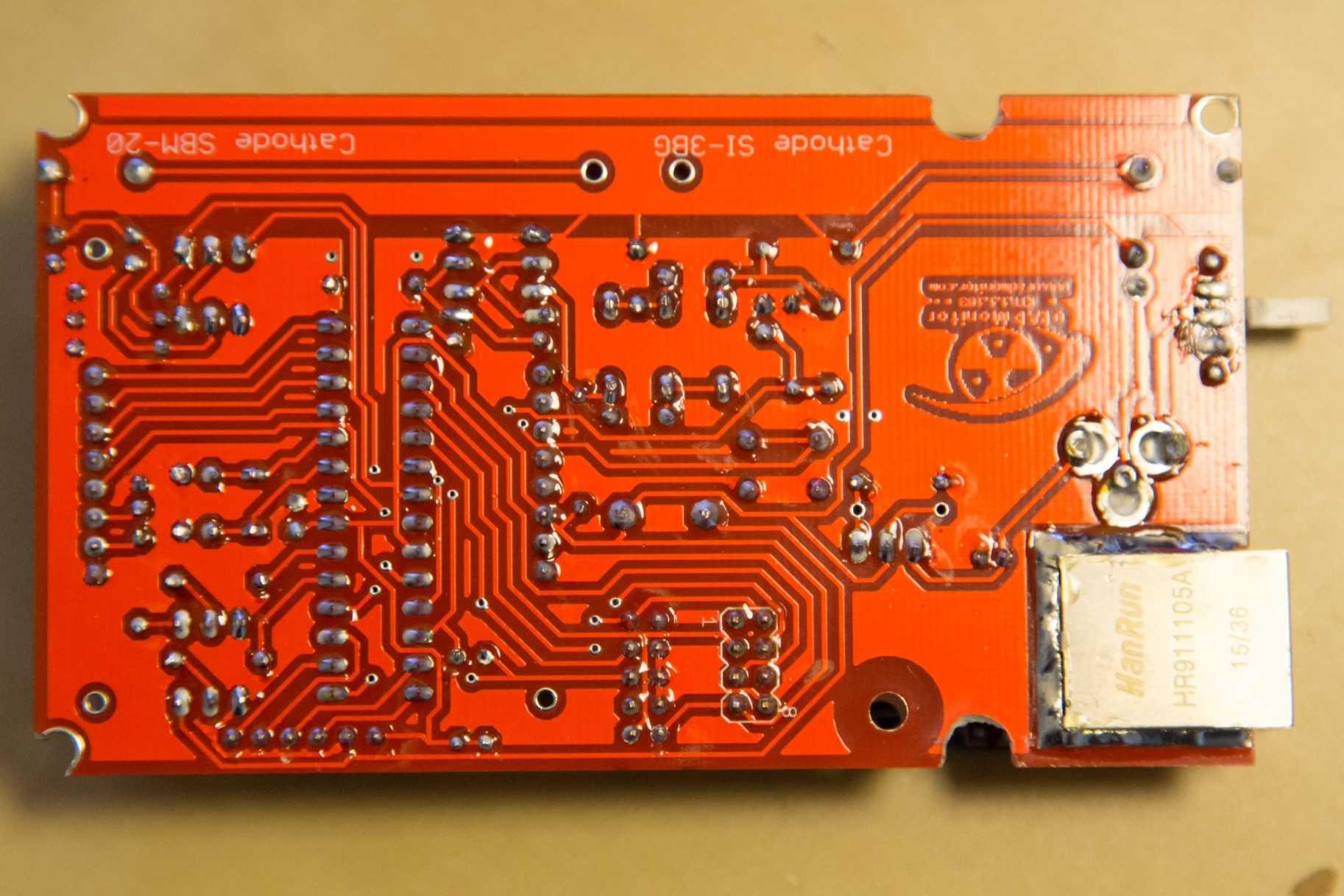
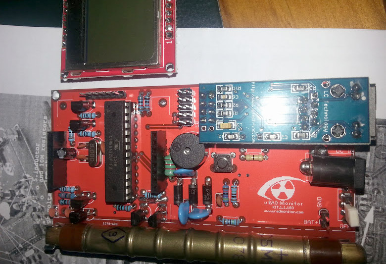
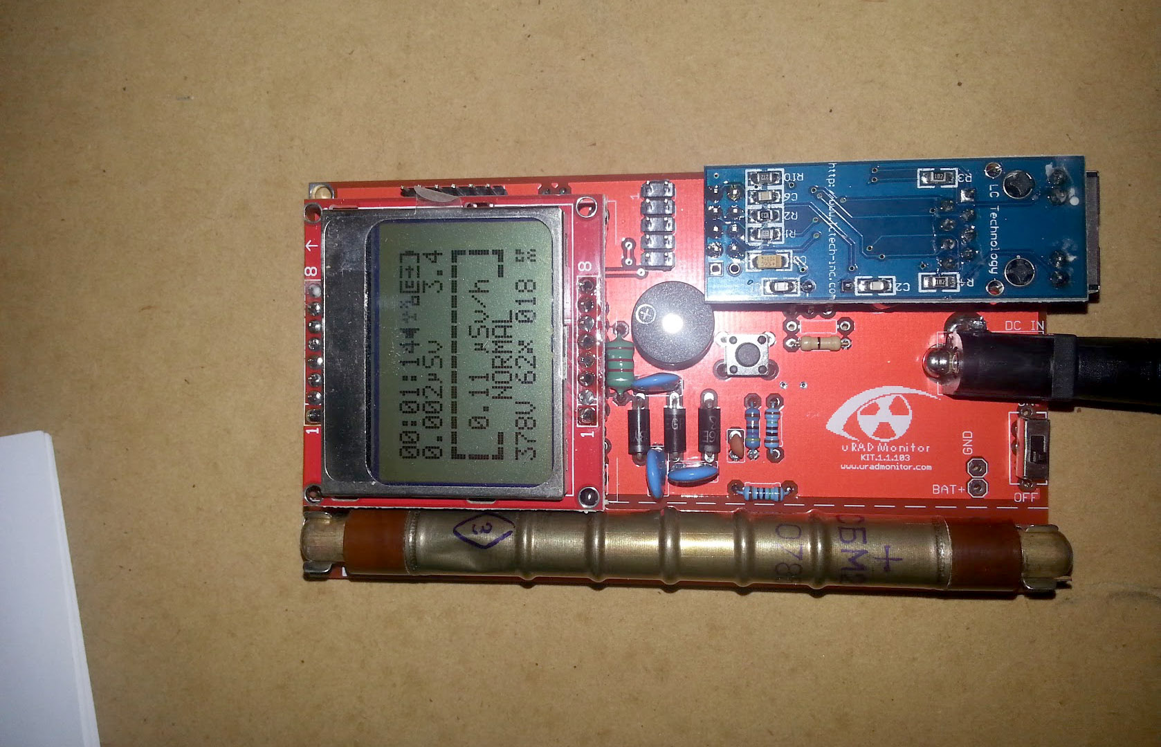
The monitor is happily working in offline mode but I would rather resolve the issue so it can be mounted in a better location.Here is a photo with the LCD removed
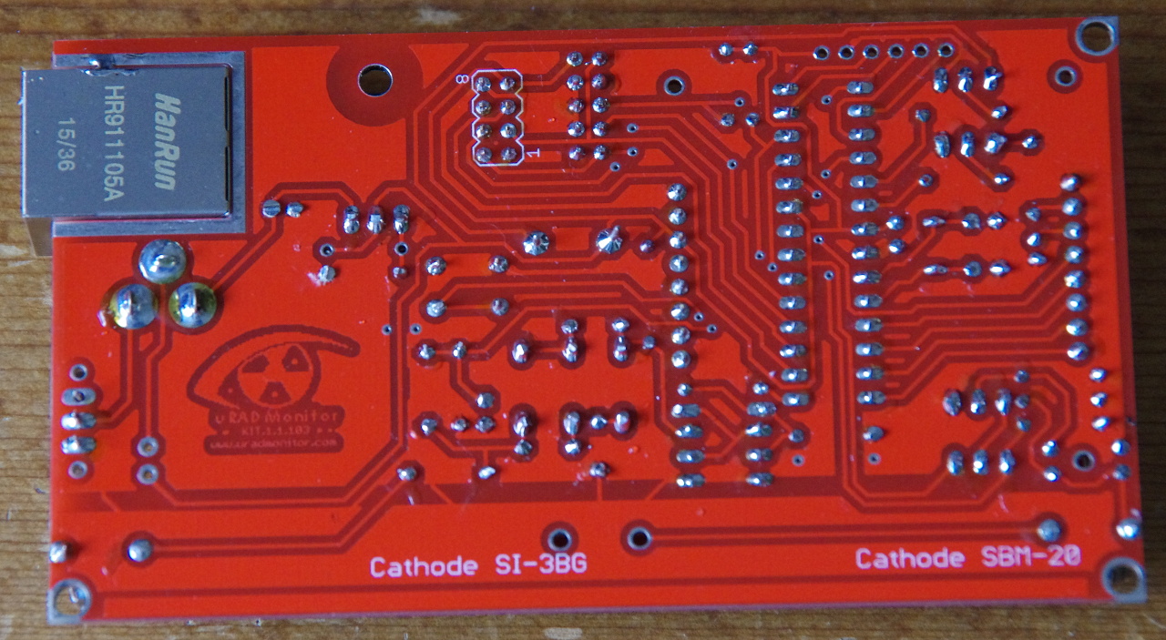
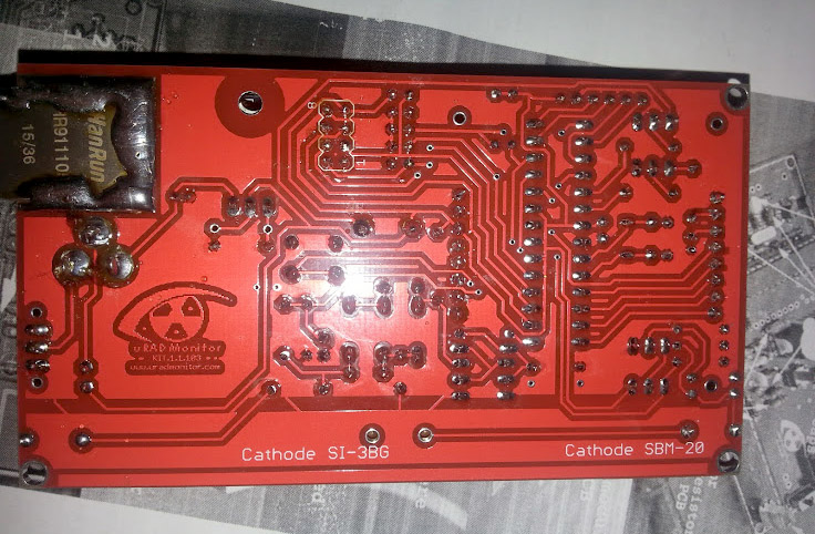
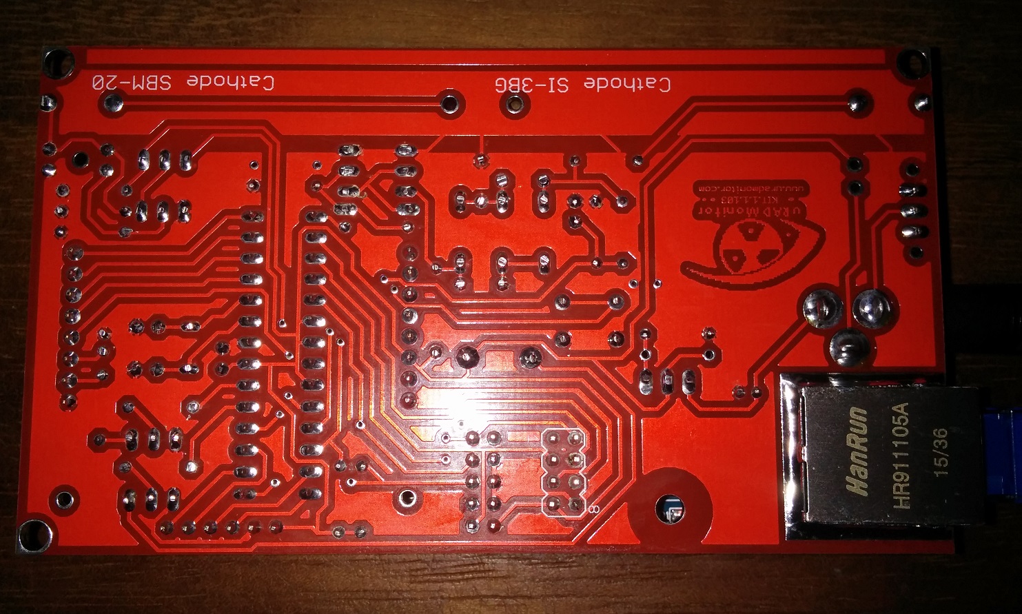
Back of board I have not cleaned the flux off yet:
I also have a BM280 module should I directly plug this in the header or run a cable and locate away from board?Also note I had to replace the switch it was a bit dodgy and bumping board would cause power to switch off. The jumper is fine as this will ultimately be powered on most of the time 🙂
July 11, 2016 at 11:12 pm #3170KeymasterIf the unit’s network interface works so you can successfully connect to it via LAN, it might mean that your router blocks the outbound packages. Please check your security settings for that. For the BMP280/BME280, I’d add it in the header, for a more compact form factor.
August 6, 2016 at 8:29 pm #3212Emmanuel_Fuste
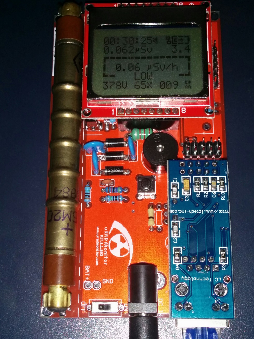
ParticipantAugust 7, 2016 at 9:26 pm #3215ParticipantThe converter is making very powerful high frequency noise (after one hour near the kit close the the computer, it hurts my ears badly).
Any idea to reduce the noise ? Is the inductance responsible for it ?
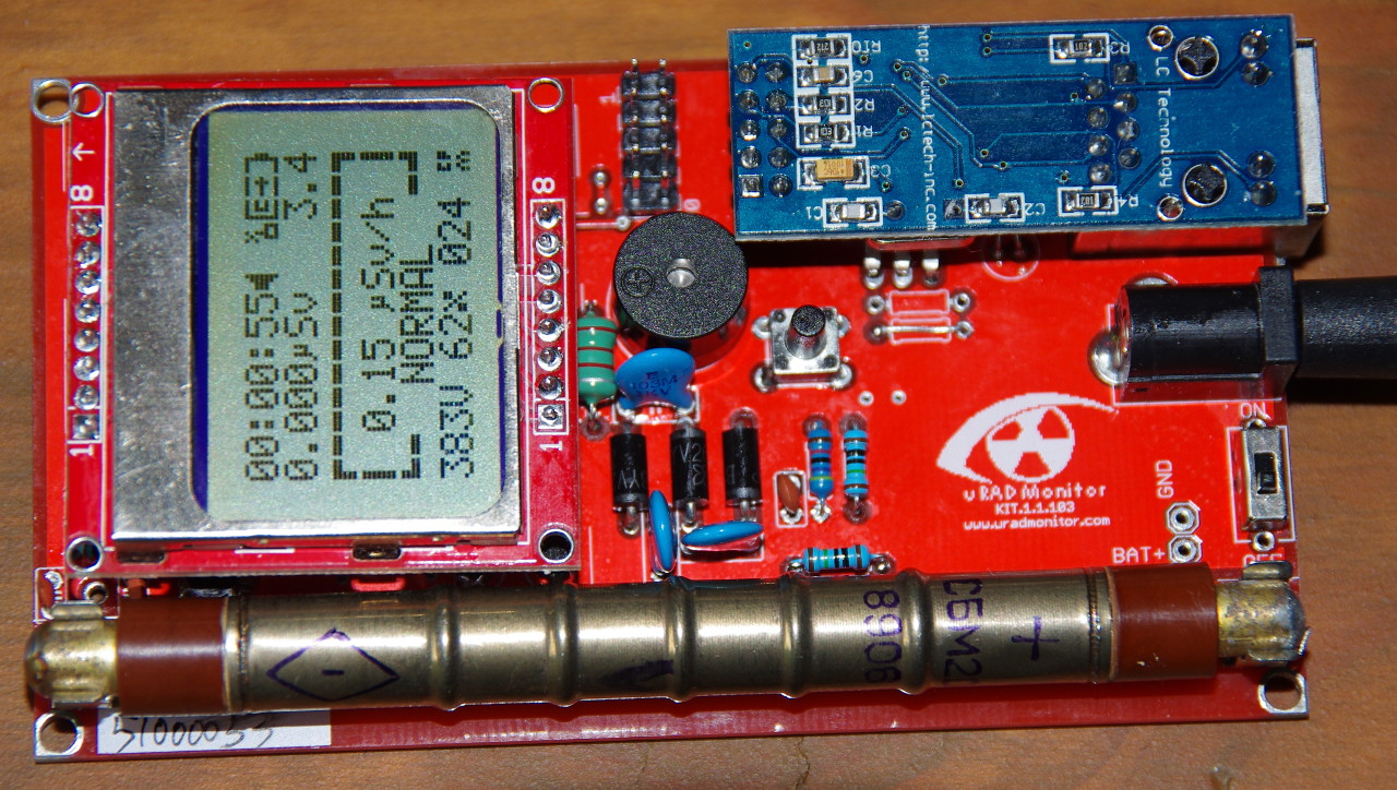
I don’t know if this is related, but my duty cycle suddenly jumped from very stable 65.4% to 69.6%. Perhaps temperature related.Edit : the duty cycle variation is clearly temperature related. Blowing air on the converter parts get me back to 65%.
August 10, 2016 at 10:12 am #3257KeymasterHello Emmanuel, your assumptions are correct. Normally the frequency of the inverter is set outside of the audible spectrum, but in your case the inductor might behave abnormally and create some harmonics. It is temperature related, as the magnetic permeability of the inductor’s ferrite core changes with temperature. You can almost use the duty cycle parameter to measure temperature.
If the sound is annoying, I can send you a custom firmware version that increases the frequency even further.
August 13, 2016 at 10:04 am #3261ParticipantHi Radhoo
Is there anything required to use the BM280 I have added mine to the kit how do you read the sensor data?Moran.
August 17, 2016 at 1:25 pm #3265ParticipantHi Radu,
I’m back online.
Thank you for your reply.
I think that I’m hitting some parameter limits of the soldered inductor or capacitors. There is a temperature related limit after which there is a big step in the duty cycle and the voltage regulation become very noisy.
Is it possible to have the exact models or parameters of the inductor and 1kv 10nf capacitors included in the kit ?
I would like to try NP0 capacitors and better rated inductor to try to get less noise an better regulation under temperature stress.
I would like to try this before pushing up the inverter frequency which could lower it yeld.Other than this minor nit (I’m a little bit perfectionist ….), the unit is up for more than ten day now and it work beautifully.
Emmanuel.
August 18, 2016 at 6:34 pm #3268Keymaster@Moran, you will need a custom firmware for that. I am working to add this functionality to the open source KIT1 repository on Github. Thanks for your patience.
@Emmanuel_Fuste, the inductor has a ferrite core, which indeed is dependant on the temperature, but I allowed enough tolerance to have optimal functionality below +65degrees celsius. However the inductor you’ve received might be faulty, I’ve seen a few with issues. I definitely agree this needs to be addressed the proper way (as I’m a perfectionist as well). Can you try getting another inductor? Specs are 2.2mH , 0.5W, 0410 Axial Lead DIP inductor. -
This reply was modified 10 years, 1 month ago by
-
AuthorPosts
- You must be logged in to reply to this topic.