- This topic has 87 replies, 21 voices, and was last updated 6 years, 1 month ago by
Justy89.
-
AuthorPosts
-
August 18, 2016 at 8:53 pm #3277
Emmanuel_Fuste
ParticipantOk
What about this one ?
Bourns PartNo. Inductance(μH) Tol.(%) QMin. TestFrequency(MHz) SRF(MHz) Min.DCR(Ω) Max.Idc(mA) Isat(mA)
9250A-225-RC 2200 ±10 45 0.25 0.97 33.8 50 27If ok I will include it in my next batch of component order (end of this week or beginning of next one).
August 20, 2016 at 8:12 am #3322uRADMonitor
KeymasterIt looks fine, the inverter’s frequency on KIT 1.1 units is set to 12.5kHz .
August 28, 2016 at 6:24 pm #3354ParticipantThe Bourns inductor is in place.
It is worse. Voltage is very unstable, duty cycle is ~70%. And the hiss is still there.
The weather is very hot.
I have anticipated the result : I have an bigger inductor to try, but I think the culprits are the capacitor. For some dielectrics, the temperature sensitivity is way more important than the inductor permeability one, and the piezoelectric effect could explain the hiss more effectively (and the Brouns inductor is supposed to be shielded).
I have ordered some (expensive) 10nf 1Kv C0G capacitors to try. They were not in stock, estimated shipping mid november…
The next days are suppose to be colder. Will see the result.You could follow the results on the website : unit 5100005F
August 29, 2016 at 4:10 pm #3356KeymasterThanks for the update, looking forward to the results..
October 1, 2016 at 8:21 pm #3549alin.m
ParticipantFinished soldering the kit, but due a bad soldering (cold join) of the MPSA42 transistor the kit would not detect anything (the HV voltage for the Geiger tube was missing).
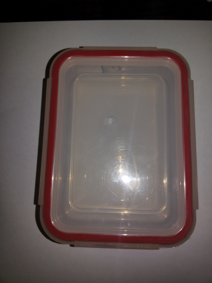
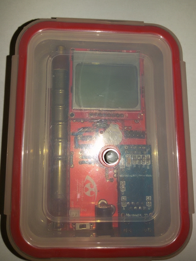
After solving this (Thank You Radu for your commitment, time and help!) I needed a case.
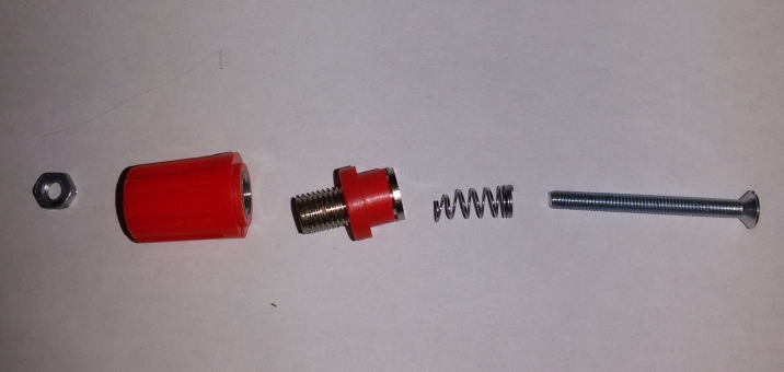
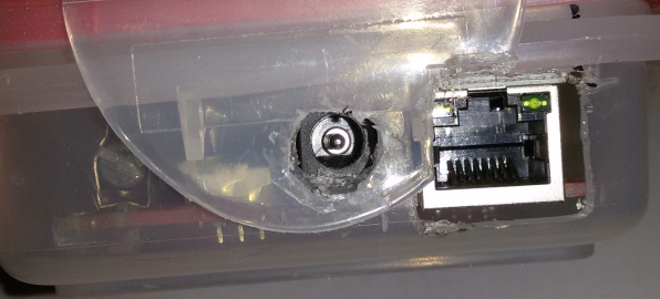
Since I don’t own a 3d printer, neither have access to one, I had limited options for a case: to buy one, and wait for it’s delivery, to make one using plastic sheets, plywood… etc OR to adapt something.I’ve chosen the last. I’ve found a plastic food container and using an utility knife and a dremel tool I cut the holes for power, network and a hole for my custom made push button rod. In order to create a sturdy push-button rod, I’ve used an old banana socket, a screw and a nut of 30 X 4mm and half spring from an old pen. I’ve put a dab of epoxy on the end of the rod, so that the metal of the rod would not damage the soldered push-button
October 2, 2016 at 10:10 am #3569wanek
Participantsorry, the links to the pictures are not working, i will try to fix this
October 2, 2016 at 10:22 am #3570ParticipantYou did a great job dude!
I’ve just received this beauty: https://www.pololu.com/product/2596.
Now I’ll be able to use the same power connector (5V) with two 5V sources. The main one will be the AC adapter and the secondary one will consist of lithium batteries. In this way, I can get the unit with me faster whenever I want! It is working also as an UPS.
In the near future I’ll use one of these: https://www.pololu.com/product/2119 so that the unit will be more versatile.October 2, 2016 at 12:22 pm #3572Participanthello everyone!

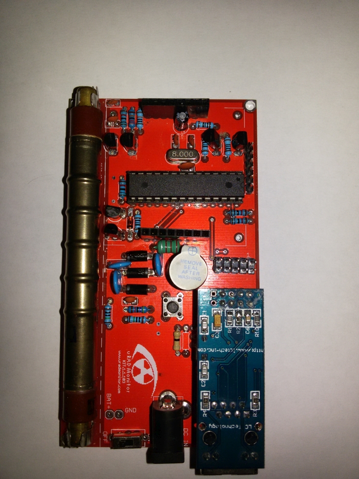
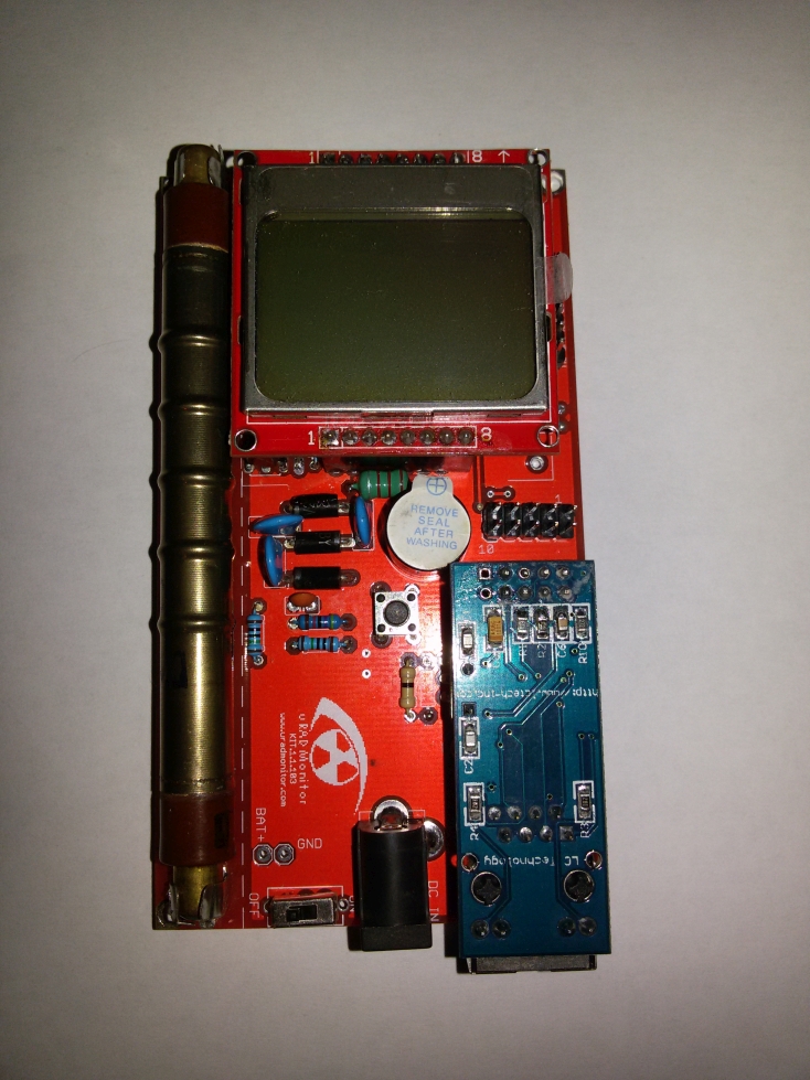
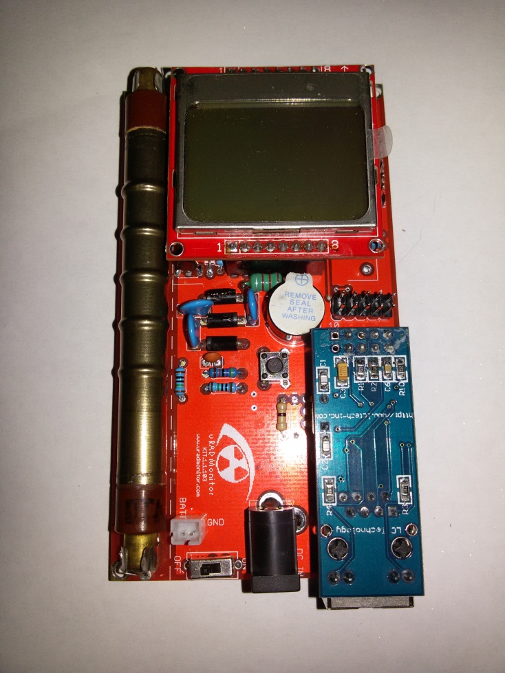
here is a post about my diy kit1, based on the v1.1.104 pcb. it was made with minor modifications / improvements regarding the original model. as radhoo said, maybe other builders will be interested in this, so i published here.

first of all, i’m a beginner in all this electronics and coding stuff, so if i wrote something stupid, please correct me. i’m always open for constructive criticism. second, sorry for my english, it is not my native language, but i’ll try to do my best 🙂
the differences compared to the original kit1 are:
– incorporated lithium battery
– built in battery charger module + micro usb port
– low dropout (0.17v) regulator
– real PoE connectivity, no additional cable / port needed on the device side, just the rj45 connector
– transparent case made from plexiglassupdated bom, with the components i used (if something is missing, please let me know):
BOM, updatedi have built 2 kits: one for me and on for a friend. ha asked to make it portable, because he will use mainly on field, as a mobile unit, outdoors and on industrial working sites.
this raised two challenge: the final product has to have a
– reliable and high capacity rechargeable battery
– a robust but not to bulky case
please note, that the components for these kits i bought from local stores, the best available quality. hence, these components visual aspect are differ from the originals, shipped with the kit1. i measured all of them before soldering, to make sure everything is up to the specs.

regarding the pcbs, after some emails, radhoo was so kind to send me 2 pieces, thank you again! because i didn’t want to ‘destroy’ these beauties, all the modifications are made without hacking the pcb.
power supply / charger / power consumption:
nowadays the “standard” power supply for handheld devices is the type b micro usb port. you can find them virtually everywhere. also, it is fairly easy and very cheap to implement into diy stuff, using these chinese modules:
battery charger, alias for the battery, probably everybody has access to some broken smartphones… although the phone or display is broken, chances are good that the battery is still functional. you just have to hook up to the output of the charging module and the input of the voltage stabiliser, it is ready to use.
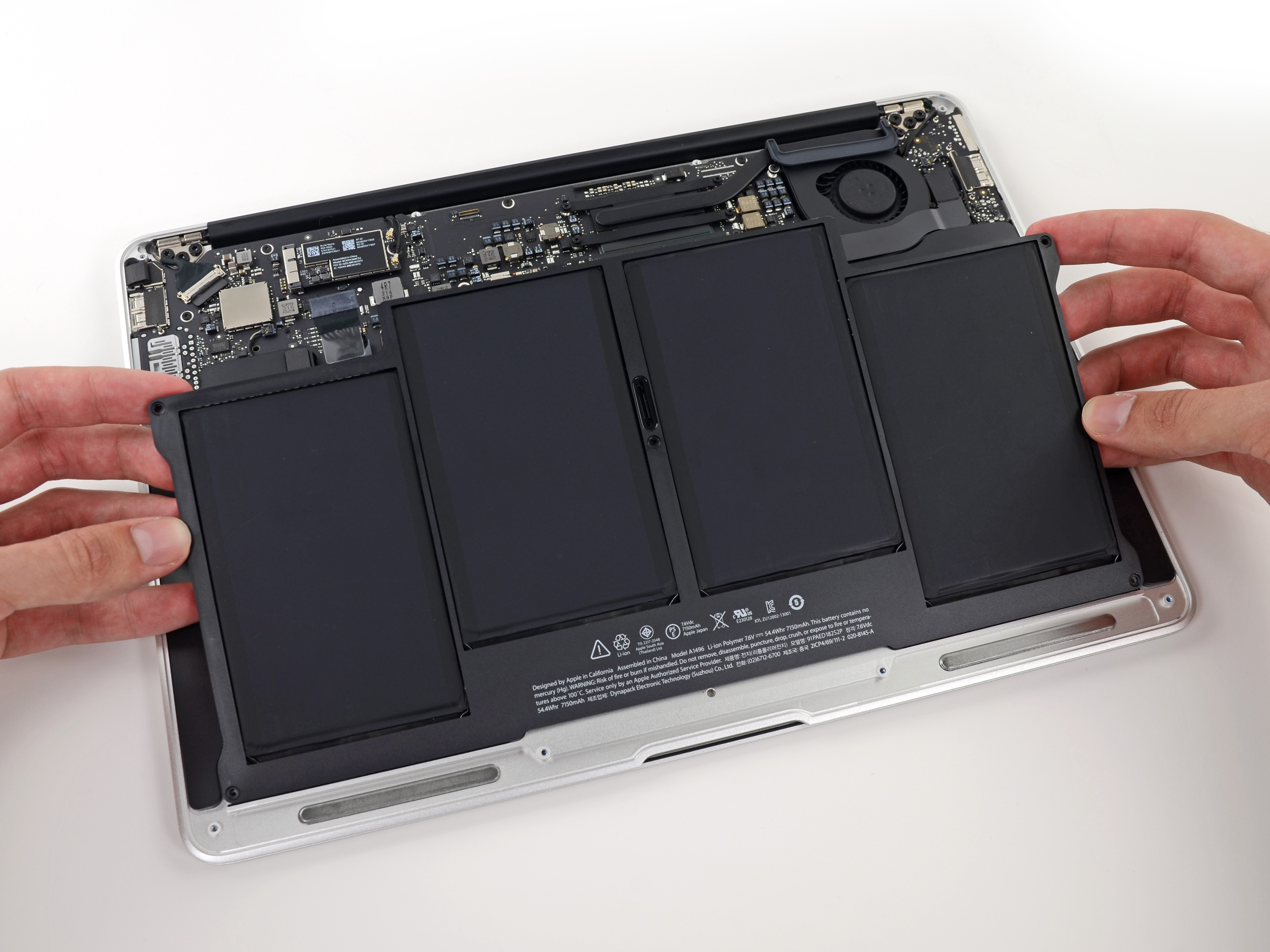
i’ve used one cell from an old macbook battery, scavenged. it contains 4 lithium cells, similar like on this site:
they are roughly the size of the kit1 pcb. this way, the charger + battery ain’t cost anything to me (0.3 euro).
to keep a safe distance between the batteries aluminum foil and the bottom of the pcb, i’ve used 4 self adhesive rubber shoes, the ones used for furniture feets.most lithium batteries have a nominal voltage of 3.6v (min 3.0v, max 4.2v). the recommended operating voltage for the kit1 is min 3.0v, max 3.3v. to take maximum use of the battery, i opted for a 3.0v voltage regulator. it has to have ultra low dropout voltage, in order to maximize battery life.
so, i had to replace the original lm1117 voltage stabiliser, lm1117 datasheet, because it has a large dropout voltage, 1.1v. (this would be 3.0 + 1.1 = 4.1v -> maybe just 5% of the overall battery capacity. not too efficient…)after a lot of searching, i bought the MCP1700-3002E/TO regulator mcp1700 datasheet. it has very low dropout, only 0.17v. it means: 3.0 + 0.17 = 3.17v, i can use around 95% battery capacity. good.
the max output current for the mcp1700 is 250mA, and the max input voltage is 6.0v. as the lithium battery never goes above 4.2v, its ok for me.to estimate the battery life, i’ve made some measurements:
(because the battery is quite old and tired, the 3700mA nominal capacity was irrelevant)
the kit1 has the following current consumption @ 3.0v (with the red led desoldered from the ethernet module):offline mode, backlight off: 36mA
backlight: 18mA
online mode, backlight off: 147mA
maximum peak current: 170mAin online mode, with fully charged battery (4.2v) it took 18 hours to discharge it to 2.9v.
discharging under 2.9v it is harmful for the lithium batteries lithium info, so even if the kit1 kept working at 2.9v, i stopped the measurement. it then took around 5 hours to fully charge the battery (from a usb port).based on the above current consumption scenarios and the measured 18 hours, it is fairly safe to estimate 50 hours uptime in offline mode. more than adequate for daily use on the field.

this regulator has a different pinout, regarding the original model. i had to make a tricky implementation, but it worked.at the moment, the only flaw is, that the kit1 keeps working even under 2.7v, over-discharging the battery. in the long run this will damage the lithium cell. the firmware should be modified to post a ‘low battery’ message to the screen and standby the unit, if the voltage drops below 2.85v. (we need to have full access to the source code to implement this)
also, it would be nice to have a voltage divider on the battery terminals (say 4.2v -> 3.0v) and implement a battery voltage monitoring function in the firmware. this way the user can have a feedback about the battery state. there are 2 unused analog pins on the mcu
 , this shouldn’t be a problem.
the MCP1700 needs 2 filtering capacitors to work properly. i’ve just replaced the original c3 with 1uf ceramic, the other one (cout) was soldered on the back side of the pcb.because the charger module covered some holes of the on / off switch on the pcb, i’ve used a different switch, placed on the right side of my case:


PoE:
for the stationary unit installed outside, i wanted to have just one single cable (for supply + ethernet).
according to wikipedia poe wiki the poe standard uses 2 modes: A and B.unfortunately, after some fiddling i’ve realised that none of these modes are implemented in the hr911105a rj45 connector, used on the enc28j60 ethernet modules. rj45 datasheet
what a pity! all the 8 pins are galvanically isolated. i needed access to pins 4+5 for dc+, respectively pins 7+8 for dc-. poe pinouts

custom made ethernet cable: on the router end has an additional usb cable, serving to inject 5v dc. this will be powered from the unused usb port on my router. the other end is just a standard rj45 connector.hacking the rj45:
it is possible to open the metal sheet on the connector. then i’ve removed some plastic with a red-hot cutter blade, to expose the pins.


the isolation transformers for rx and tx are clearly visiblecleaning and soldering the wires to the selected pins was easy. for tapping i’ve removed one of the lateral side tin. after putting some layers of insulation to the exposed pins i’ve closed the connector.


the terminal wires were soldered to the appropriate INPUT pins (+5v and gnd) on the micro usb charger module. now i have a real poe module!
attention:
do not solder the +5v cable to the charger module OUTPUT, because it will overcharge the lithium battery! lithium batteries, if charged beyond 4.3v can explode or catch fire!of course, this modification doesn’t deal with the two 75 ohm resistors, which kinda “short” the usb port.

but if you do the math: 2 x 75r = 150r. for 5v / 150r = 33mA extra current consumption for the usb port. the usb port standard specifies at least 500mA / port. the whole device does not absorb more than 200 mA, i think this is on the safe side.
regarding the heat production on the two 75 ohm resistors:
0.033A x 5v = 0,166W total. there are 2 resistors, so this is 0.083W / resistor. even if the resistors will burn out, i do not care, they are useless in this configuration (i think).please note: using 5v dc with poe is not recommended on long cable runs, because, when load applied, the voltage drops quickly. in my case, i needed 5m ethernet cable. with the device connected, the 5v dropped to 4.3v. this means, that the charger module will output max 4.0 volts, so the battery will be never charged to 100%. this is not a problem for me, as the router will continuously supply the power. for much longer cables, one should consider using a dc to dc booster between the usb port and ethernet cable to compensate for the voltage drop.
bme280:

the v1.1.104 pcb has a nice feature, the extension port. i’ve populated this port with a bme280 module. bme280 specs
you can buy one here: bme ali
these sensors are very high quality and one can obtain a lots of info, with proper code implementation:
– temperature
– pressure
– altitude (uncalibrated)
– relative humidity
– dew point
– heat index (shadow)
– heat index (sunlight)i’ve wrote a small arduino sketch to display all these values, using the SparkFunBME280 library. bme280 sketch

unfortunately, at the time of writing this article, the uradmonitor source code (v117) is not fully open. we have to wait for radhoo to implement this sensor, or much better, to publish the full source code on github.
case design:

for the device to be fully usable outdoors and to have a better visual experience, needs a case. i’ve designed the case in corel draw x8. made two very similar models, one for wall mounted fix station, one for portable device. despite my very limited knowledge in corel, i managed to finish it with quite good results. it was then laser cut from 3mm clear plexiglass.

since the enc28j60 chip produces a lot of heat, in a closed case this would deteriorate the temperature readings.
i’m interested in the REAL outdoor readings. if the temperature value is not correct, all the other values are useless. the humidity calculation formula is also based on temperature. accordingly, i had to assure a very good ventilation for the sensor.
designed a lots of ventilation holes on strategic parts of the case. these are circles 1.5mm in diameter. this is the smallest diameter the laser can cut, without melting too much plexi around. i hope the insects will not pass these holes. they will surely try. when winter coming, a ‘heated’ hotel is very attractive…
as hot air always goes up, the components arrangement is not very fortunate for the sensor, since it is placed exactly above the biggest heat source in the kit1.
i decided to mount the whole device upside down to the wall, this way the bme280 will be under the ethernet module. the ventilation holes should produce a chimney effect, that will take care to transport the air from bottom to top. theoretically, the sensor will always receive the unheated air from outside, obtaining correct readings.
i will test this theory when the device is mounted on the wall, placing an external temperature sensor near the case, and compare the 2 values.while used as a fix station, the micro usb port will be out of order. hence, it will be covered with a cap, to keep the bugs at bay.
if anyone is interested to build one of these case, here are the corel draw x8 files:
fixed station with bme sensor
portable, without bme sensor
i will add new photos when it will be installed in its final place. for high resolution pictures you can visit: album
thank you radu for all the big effort and helpful attitude in this worldwide project!
thanks for reading,written in 2016, oradea.
 October 2, 2016 at 12:42 pm #3573Participant
thanks!
the 5v Step-Up/Step-Down Voltage Regulator indeed seems very useful.
but i’m not sure what is the point of the first product, the TPS2113A Power Multiplexer?October 2, 2016 at 1:43 pm #3574Participantso, i just put together the uradmonitor kit1, but i don’t have an isp programmer to upload the hex. but i have a lots of arduinos around…
this guide will show you how to upload the hex file to the uradmonitor kit1, using an arduino uno r3 + windoze
you will need:
– arduino uno
– 6 male to female jumper wires
– latest arduino ide
– hex fileplease note: this article is for arduino uno r3, i will not explain here how to use other models. however, with a little googling + thinkering it is not complicated to adapt. for other mcu you can start here.
attention:
the nokia 5110 display and the enc28j60 ethernet modules max voltage is 3.3 volts!
the arduino uno uses 5 volts, so, to protect the display and ethernet module, it is advised to remove them from the kit, before hexing. (however, sometimes, i didn’t remove the ethernet module and it survived)also, be sure to use tightly fitting jumper cables, you do not want to lose power or data while uploading the hex file! do not move / touch the setup while uploading!
steps:
0) download and install the latest arduino ide + drivers (arduino.cc)
1) open the ide, and go to: file > examples > arduinoisp and open the arduinoisp sketch
2) uncomment line 81 (// #define USE_OLD_STYLE_WIRING)
3) note the com port number in: tools > port (you will need this number later)
4) upload the sketch to the uno r3
5) close the arduino ide
6) remove the display (and ethernet module) from the uradmonitor board
7) unplug the arduino usb cable from the pc. connect the jumper wires as follows (see image):

uno -> kit1
gnd -> 4
5v -> 2
pin 10 (ss) -> 5
pin 11 (mosi) -> 1
pin 12 (miso) -> 9
pin 13 (sck) -> 7it’s a good idea to write the arduino port numbers on the pcb, for future software upgrades:

8) double check the wiring between the uno and uradmonitor

9) copy ‘avrdude.conf’ file from*: c:\Users\wanek\AppData\Local\Arduino15\packages\arduino\tools\avrdude\6.3.0-arduino6\etc\
to: c:\Users\wanek\AppData\Local\Arduino15\packages\arduino\tools\avrdude\6.3.0-arduino6\bin\*please note: the path can be slightly different, based on the ide version
10) copy the uradmonitor hex file to: c:\Users\wanek\AppData\Local\Arduino15\packages\arduino\tools\avrdude\6.0.1-arduino6\bin\ and rename to: ‘uradmonitor.hex’
11) open a terminal (go to start > search, type ‘cmd’ then press enter)
12) copy – paste this in the terminal (replace “wanek” with your user name):
cd c:\Users\wanek\AppData\Local\Arduino15\packages\arduino\tools\avrdude\6.3.0-arduino6\bin\13) connect the arduino to the pc usb port
14) replace xx (use notepad) in step 15 and 16, with the port number you noted in step 4.
15) copy – paste in the terminal:
avrdude -P COMxx -b 19200 -c avrisp -p m328p -v -e -U lfuse:w:0xdc:m -U hfuse:w:0xdf:myou should see something similar:

16) now enter this:
avrdude -P COMxx -b 19200 -c avrisp -p m328p -v -e -U flash:w:uradmonitor.hex -U lock:w:0x0F:m
it will take a while, but if you’re seeing this, it means you have succeeded!17) unplug the usb cable, remove the jumper wires, remount the modules and power up the device. it should start up with the uradmonitor logo. now you can connect to the global network.
attention:
if something went wrong, and after hexing there are verification errors, answer no and try again. check the quality of the wiring, do not use too long cables (max. 20cm)
i’m not sure why these errors occur, but once i answered yes, and the process apparently halted. so i closed the terminal and after that, the microcontroller is not working… probably i’ve bricked it.
radhoo has some very detailed article about mcu flashing, here
written in 2016, using arduino ide 1.6.11, on windoze 1607.
October 2, 2016 at 2:29 pm #3575ParticipantWell… I will build a “docking” station later… The multiplexer autoswitch is switching between the two inputs. The primary input will be powered from the AC input, while the secondary input wil be powered is powered from battery. The multiplexer and the Kit1 will be in the same enclosure.
October 3, 2016 at 3:25 pm #3644Keymaster@wanek congrats on your excellent work that went on the uradmonitor blog: https://www.uradmonitor.com/building-kit1-extra-features/
October 4, 2016 at 12:17 pm #3645Participantthank you!
November 19, 2016 at 9:38 pm #3757ParticipantHello, I’m back.
1kV C0G caps in place.
Duty cycle is now 5% lower in same temp conditions. As C0G is not subject to derating or aging at high voltage (as X5R/X7R) and is more stable across temp variation, the inductor should now be the only/dominant cause of mean duty cycle variations with temperature variation.
Duty is very stable.
Hiss is lower.
Direct on screen voltage readout seems to be more stable too. Need to be monitored on a longer period.
I have stronger VHBCC-222J-01 too, will try later for fun.
My unit is online for near six months. I’m very happy with the overall result.
It’s time to add a Bosch sensor to it !November 23, 2016 at 10:42 am #3758KeymasterLooking forward to that! Thanks for the feedback
-
AuthorPosts
- You must be logged in to reply to this topic.