Home Forum Hardware KIT1 v102 resistors

Viewing 5 posts - 1 through 5 (of 5 total)
  • Author
    Posts
  • #3048
    Curt
    Participant

    On the .102 version of the kit, I was not sure to do with R7 and R13. The instructions for the .103 board say to leave R7 out. Is that the case for .102?

    • This topic was modified 7 years, 10 months ago by uRADMonitor.
    • This topic was modified 7 years, 10 months ago by uRADMonitor.
    #3050
    uRADMonitor
    Keymaster

    Hi Curt,

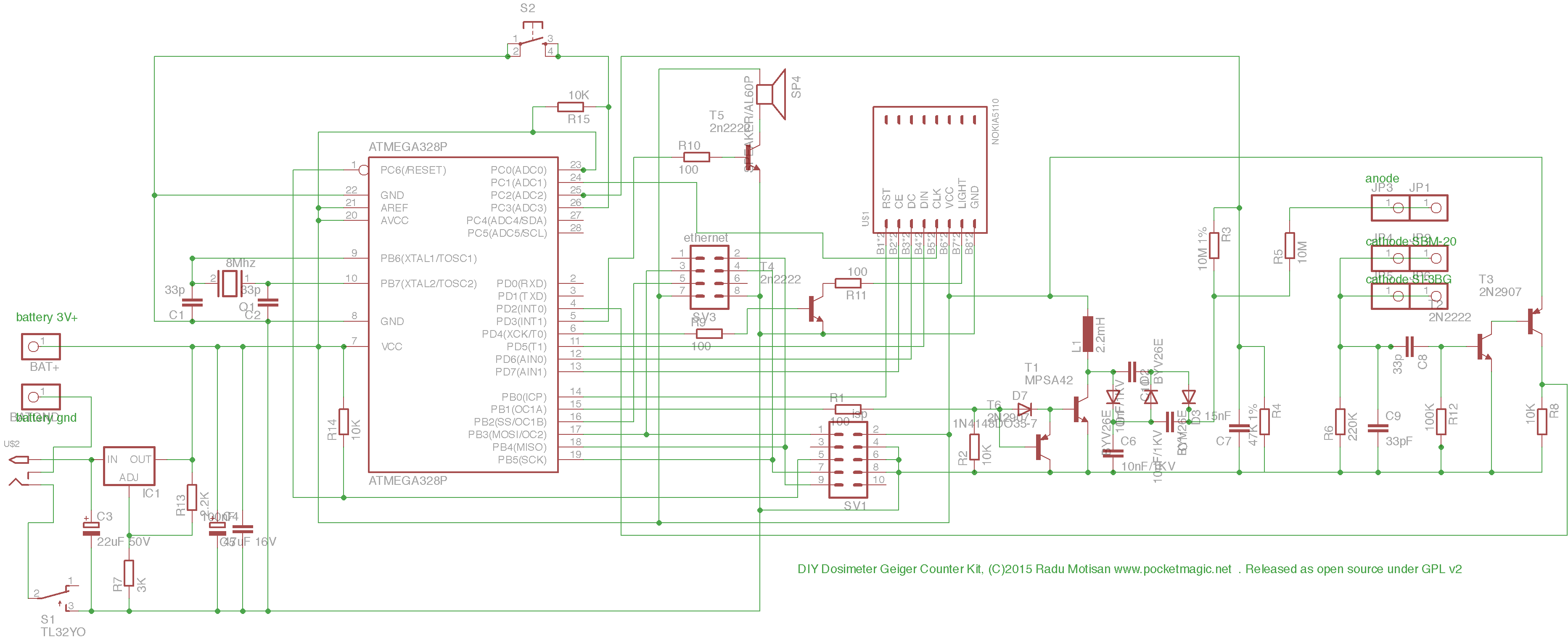
    Here is the diagram of v102 : http://www.pocketmagic.net/wp-content/uploads/2015/10/uRADMonitor_KIT1.1_sch.png

    The IC1 is the 1117 regulator, the ADJ pin needs to be connected to GND, that goes through R7, so make sure you replace it with a wire.

    The R13 must not be connected. On the v103, the naming of R7 and R13 is reversed, wish I didn’t do that.

    The idea with these resistors is that instead of the LM1117, you could use the LM317, and the resistors were chosen to give out 3V. On a next revision (104), these will be removed completely.

    #3063
    Curt
    Participant

    I installed the 2.2k resistor in R13 and left out R7. It came online ok when I powered it up. So you are saying that I should cut out R13 and put a jumper in place of R7?

    #3065
    Curt
    Participant

    I removed resistor 13 and put the jumper in place of 7. That made a heck of a difference. Screen shot clearly shows when I made the change.

    #3067
    uRADMonitor
    Keymaster

    That looks good. Sorry for the confusion with the resistors, I’ll make sure to correct it in the next version of the PCB. As said, it was to preserve backwards compatibility for using the LM317 instead of the better LM1117 . And backwards compatibility is a pain, nearly every time.

    Radu

Viewing 5 posts - 1 through 5 (of 5 total)
  • You must be logged in to reply to this topic.