- This topic has 87 replies, 21 voices, and was last updated 6 years, 1 month ago by
Justy89.
-
AuthorPosts
-
April 25, 2016 at 12:13 pm #2913
uRADMonitor
KeymasterThis thread is started to help those that prepare to assemble a solderable KIT1.1 including the units distributed through the indieGogo campaign. Feel free to post pictures and questions here, but also share know-how and assembly experience with others.
LE: there is an ongoing competition, for all those that post their construction here. We’ll have some voting in place, and the nicest build wins a model A2 detector. DIY units go as well.
-
This topic was modified 10 years, 2 months ago by
uRADMonitor.
-
This topic was modified 10 years ago by
-
This topic was modified 10 years ago by
-
This topic was modified 10 years ago by
June 2, 2016 at 9:41 pm #2963rbrt
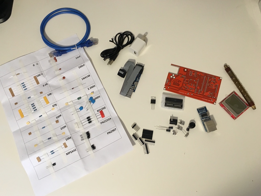
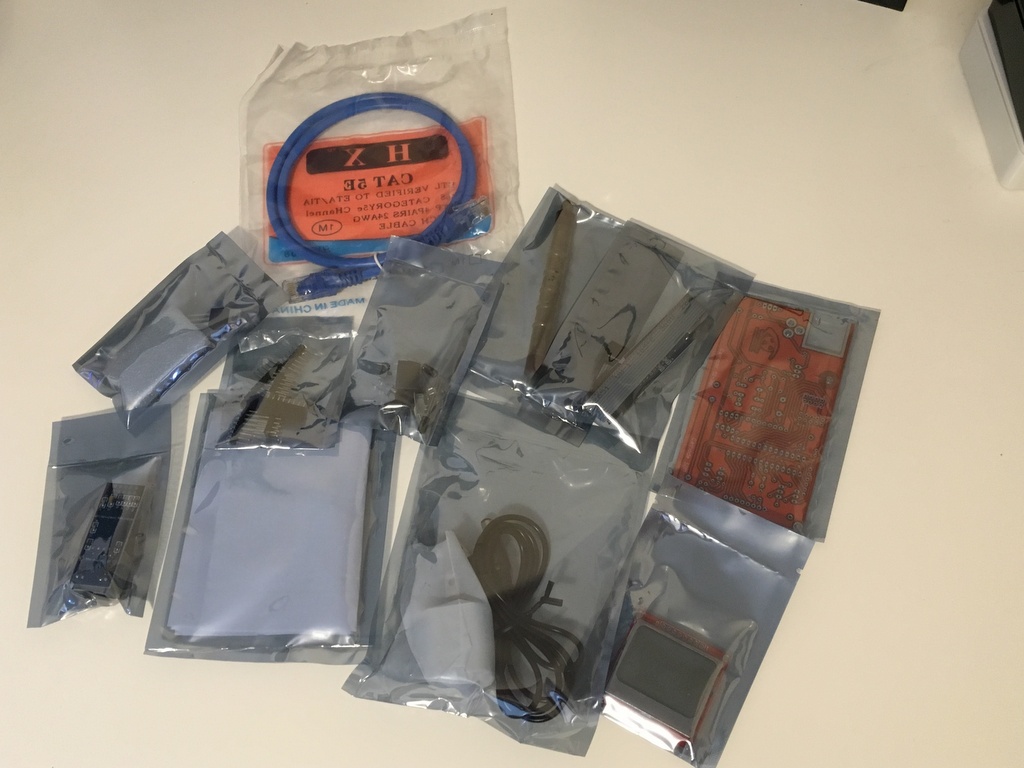
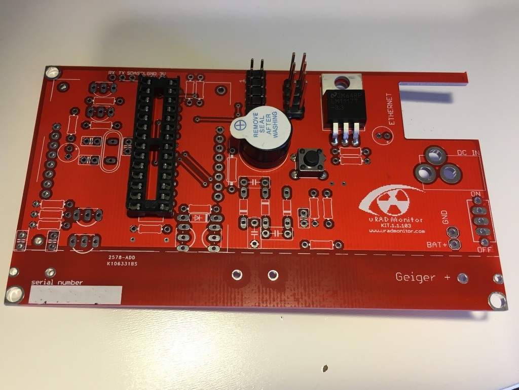
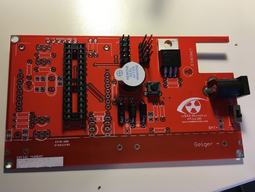
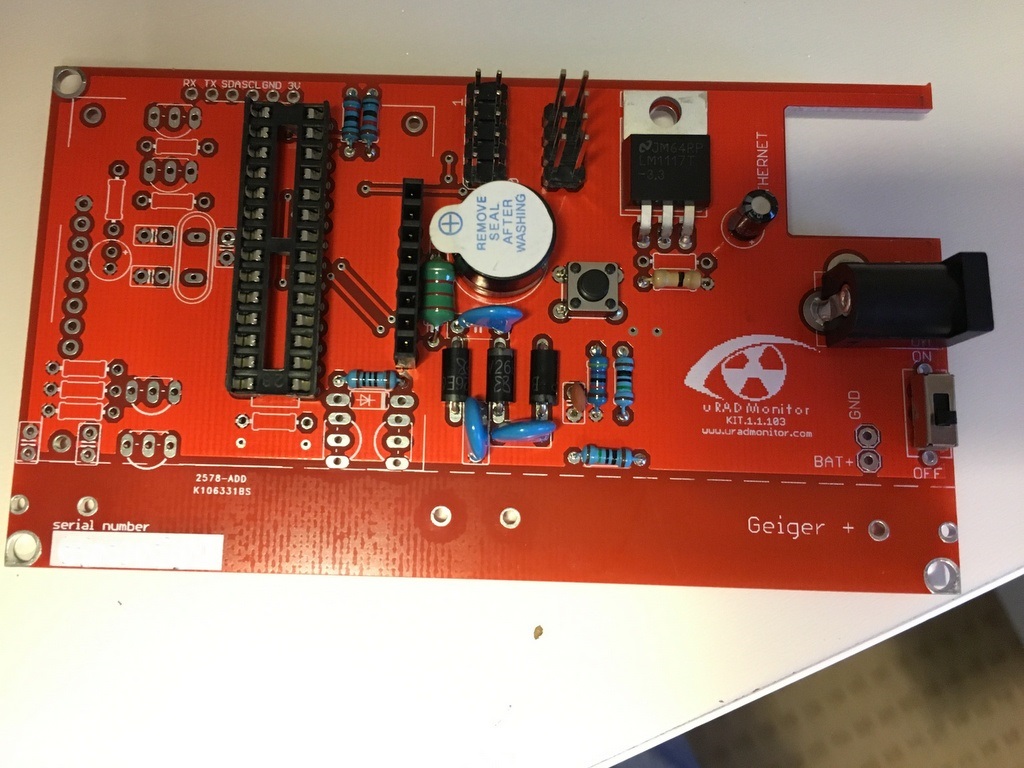
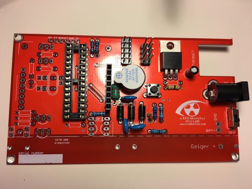
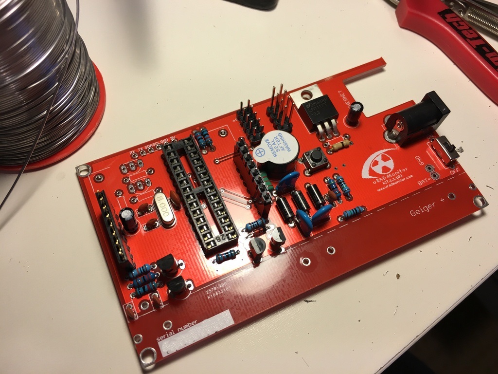
ParticipantMy Indiegogo KIT 1 arrived today and I’ve just finished assembling it, here are some photos of the assembly:
-
This reply was modified 10 years, 1 month ago by
rbrt.
June 3, 2016 at 6:03 am #2965Keymasterawesome! just changed the coordinates as per your request! thanks for the photos, it looks great
June 9, 2016 at 2:47 pm #3007Sulley
ParticipantHello!
I’ve just built my kit and it’s working.
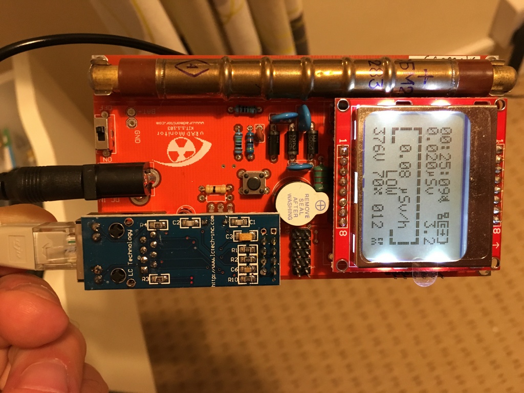
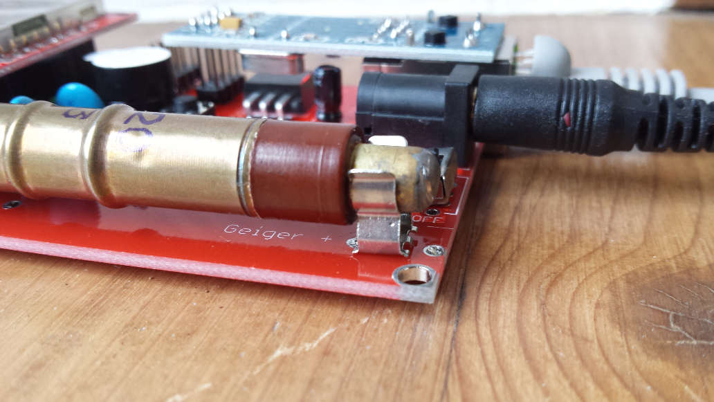
I was just looking at rbrt’s pictures and I’ve noticed that he might have the tube in the wrong orientation. The tube does require proper orientation (plus side to plus connector on the board), right? Or it doesn’t really matter?
June 10, 2016 at 9:52 am #3008KeymasterThat’s correct Sulley! Anode must be connected to the GEIGER + (Just emailed him about it.)
Feel free to post pics with your own construction!June 10, 2016 at 4:08 pm #3017ikmaak
ParticipantI just posted my experience in assembling the KIT1 on my blog, with some pictures.
The link is: https://ikmaak.nl/eenblog/2016/06/10/uradmonitor-campaign-update-2/If there is anymore info you would like, or know the answers to my issues, please let me know.
Thanks and congratulations Radu, for completing this part of the campaign. Nicely done!
June 10, 2016 at 4:41 pm #3018KeymasterHello Ruben, those are some excellent pics, please post a few in this thread as they definitely have a chance for winning! Some guys already did a 3D printed case, I’m trying to bring them here as well, so people can actually benefit of the beauty of open source. Got your requirement on BME280, and it’s now on my list.
June 10, 2016 at 7:20 pm #3021Tino Neubauer
ParticipantHi guys .
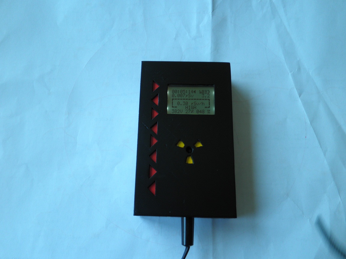
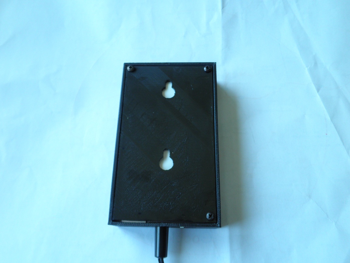
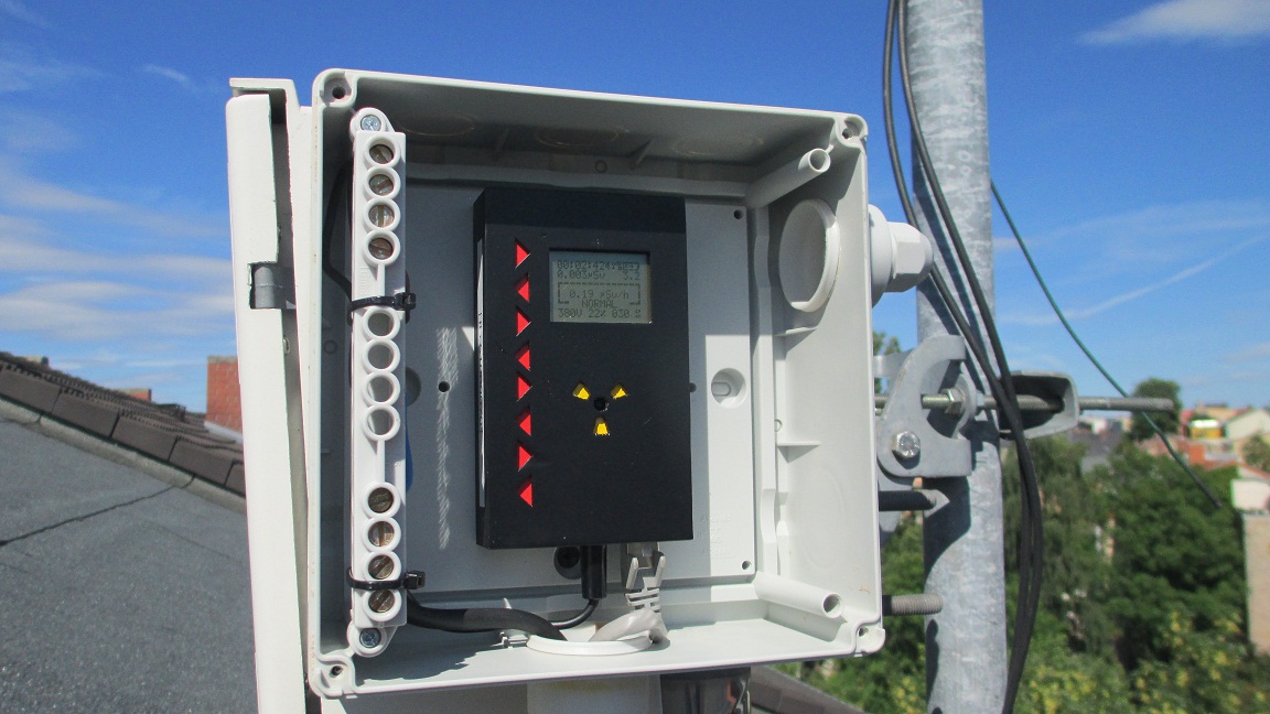
Here is my DIY KIT 1.1 with a housing made with my 3D printer and Tinkercad.
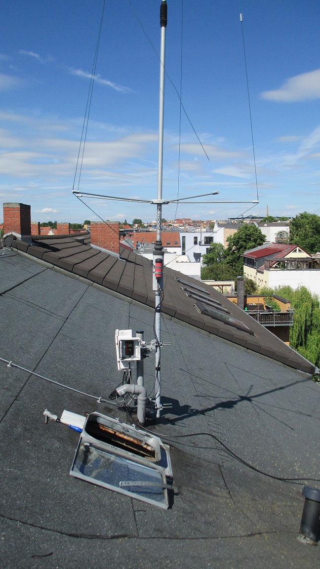
It is mounted on the bottom of my Ham Radio HF antenna. This is a bad idea, because the 100W from my transceiver generated interference ;-(
I think, i try another place few meters away from the antenna.
The unit number is 51000079 and it is located in Halle ( saale ) Germany.73 Tino DM2NT
-
This reply was modified 10 years ago by
Tino Neubauer.
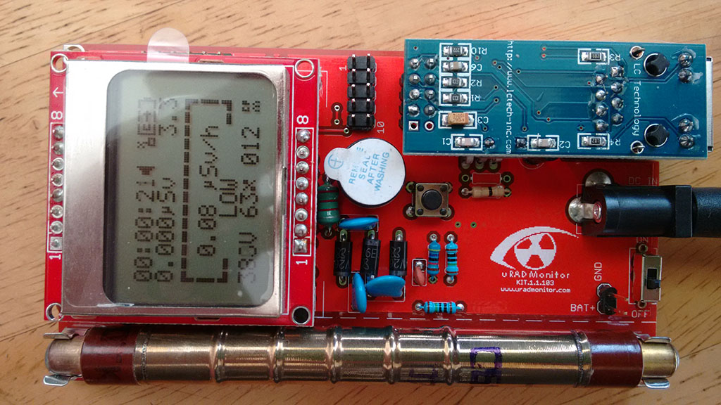
June 12, 2016 at 9:26 am #3029ParticipantThanks for the note about the orientation of the tube, wasn’t sure if it was important. I originally based it on the photos from this blog post which shows the tube installed upside down: https://www.uradmonitor.com/model-kit1-production-ready/
I’ve swapped it around now and am looking for an enclosure to mount it in. Are there any specific requirements? Plastic, metal, height off the ground outdoors? Also if I was to add something like the BME280 would there need to be holes in the enclosure rather than having it watertight?
Regarding powering the device, something like this kit would be very useful: http://www.tp-link.com/en/products/details/cat-4794_TL-POE200.html
It allows you to inject a 12V into the spare cores on an Ethernet cable and pull them out at the other end (it’s an injector and splitter, and not a standard 802.3x POE).
June 13, 2016 at 8:49 pm #3032KeymasterHello Robert, sorry about that picture, didn’t notice it. I’ll have it replaced when I get the chance.
While a Geiger tube is just a two electrodes discharge tube and there is electronic charge requirements in that regards, the polarity is still important because of optimisations made in the materials used: the cathode is a large surface material responsible of electron emissions, while the anode works as a charge collector and is usually a tiny wire.
For some tips on installation, please see the article for model A, the facts there apply to KIT1 as well, except that the KIT1 doesn’t have an enclosure: https://www.uradmonitor.com/tips-for-installing-the-uradmonitor-unit/
If you plan to use a BME280, you’ll need it to communicate with the air outside. Some holes (at the bottom) are needed. For POE you can use a passive one like:
http://www.ebay.com/itm/Ethernet-PoE-Adapter-Injector-Splitter-Kit-Supports-5-12-24-48V-Power-over-/172236498811?hash=item281a18677b:g:8ykAAOSwepJXV9P1Or one that has built in DC-DC converters to increase the voltage for transport and then reduce it back to 5V at the end.
June 14, 2016 at 3:01 pm #3033ParticipantNo problem rbrt, I’ve made a same mistake for a few minutes. Was getting to low readings so I double checked.
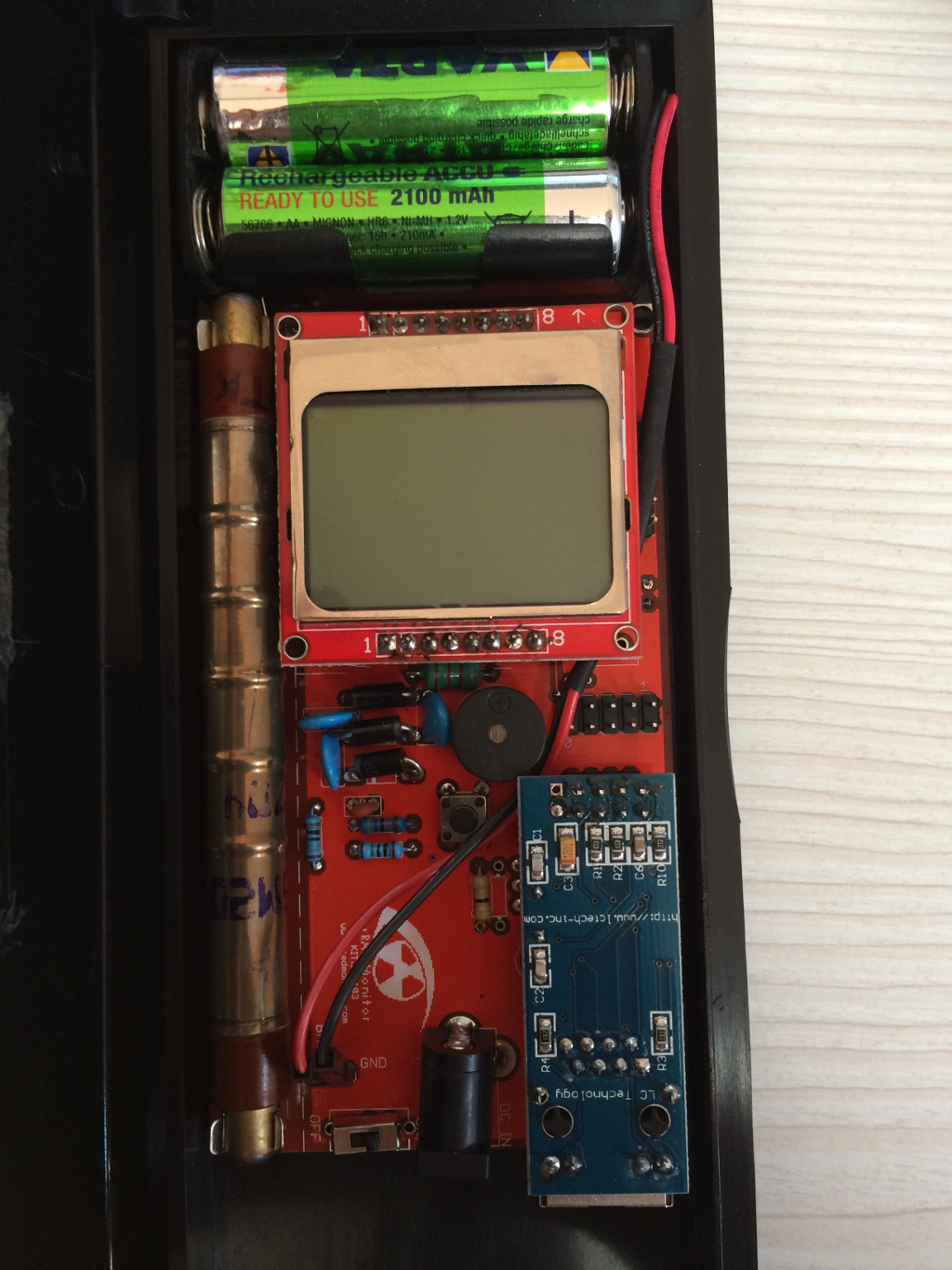
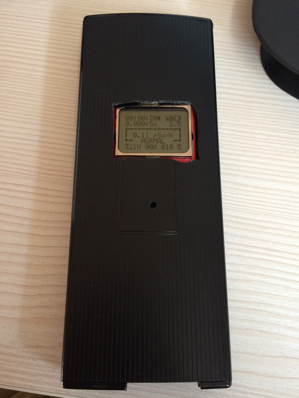
Anyway, here’s my unit. I was to eager to finish it and I didn’t take progress pictures. It’s not going to win any beauty contests, but it works! Here it’s shown as working on batteries. Wonder how long two AA will last.
Also, I don’t have a 3d printer but I have a Dremel, so I reused a spare pencil case which fits perfectly with room to spare for batteries. It has just enough room for the ethernet and power plug, so it can work as a stationary too!
I’ve tested the unit for a few days now. I will keep it offline for some time, until I find a proper place to mount it.
I have the bme280 ready and waiting, too.
Cheers
-
This reply was modified 10 years ago by
Sulley.
Attachments:
June 15, 2016 at 8:15 am #3037Mads Barnkob
ModeratorI got the kit all soldered up and are now waiting for a handheld enclosure to arrive from Hong-kong, so it will be a little while before I can show it off 🙂
A few suggestions to the manual for the KIT1.
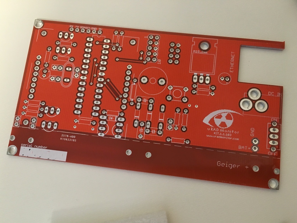
The two pictures of the component layout is too crowded, it is in some cases impossible to read the component name on it (R14, R15 etc)
The overall print quality is not up to par, the schematic is very fade at the edges of the paper.
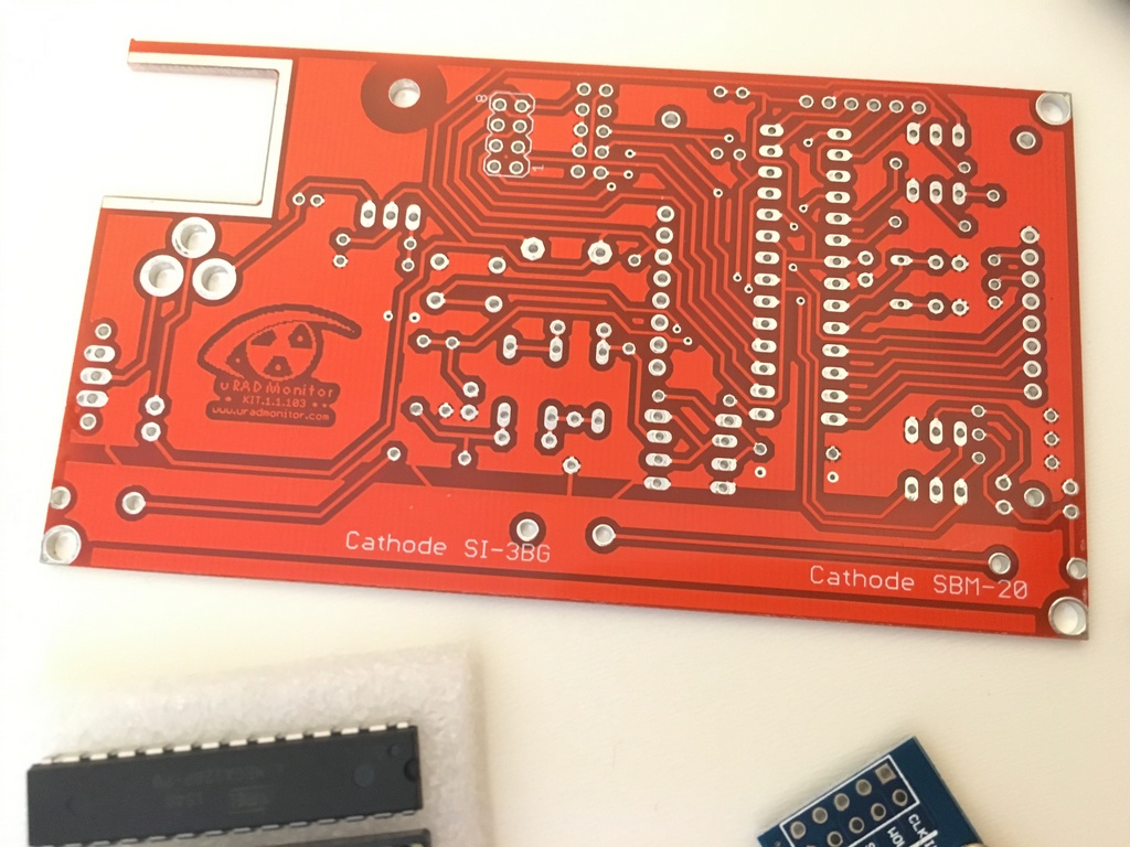
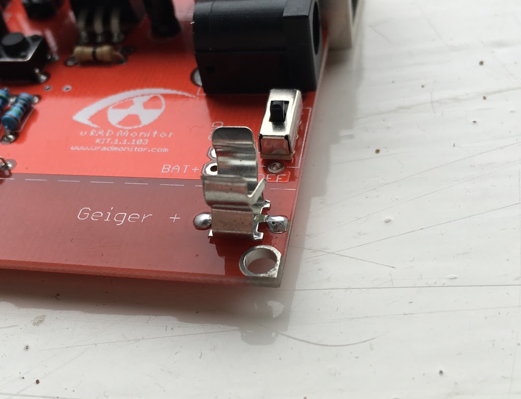
The only thing I could wish different for the PCB would be that the corner holes had enough space for a nut or bolt without being dangerously close to the end terminals for the GM tube.
Else it was pretty much a walk in the park to solder the unit and it was online within a couple of hours from unpacking the box 🙂
June 16, 2016 at 3:05 pm #3038Olivier Baumgartner
ParticipantI received the kit…. and soldered it…. GREAT !
Really “Plug & Play”
I was very pleased to see all resistors and caps well identified on a sheet of paper ! very usefull!
Just few difficulties :
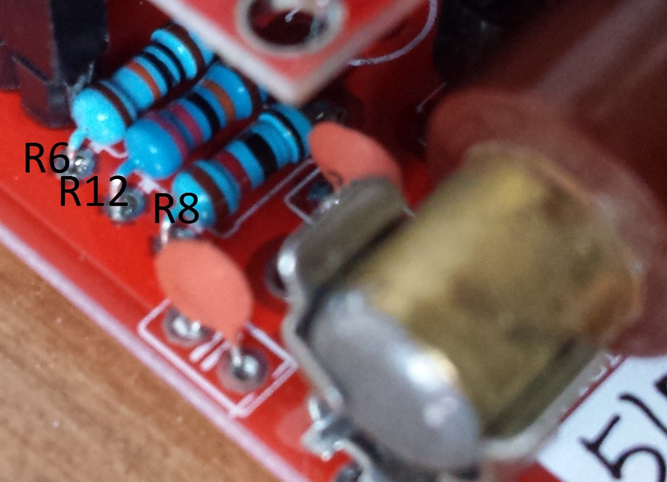
R8/R12/R6 : not very easy to identify on board (See picture)
A picture showing how to choose pin to sold for geiger can help someone
Very nice work, I’m very glad !A first run unconnected to network and test with radio source : All OK
-
This reply was modified 10 years ago by
Olivier Baumgartner.
June 17, 2016 at 8:20 am #3043KeymasterHey guys! Thanks for the feedback. Next edition will have better silkprint for those resistors, I’ll also take care to improve the manual’s print quality .
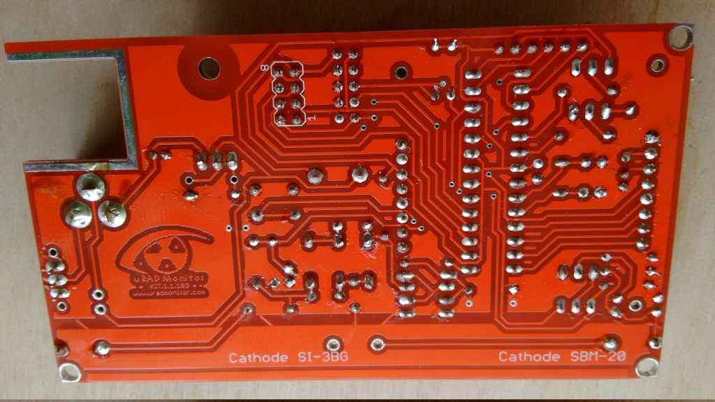
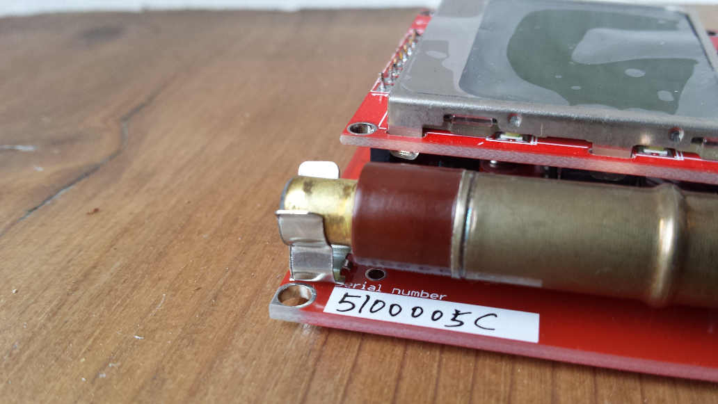
June 20, 2016 at 7:42 am #3049ParticipantI chose to solder the tube connectors slightly differently. I first flattened out the pins then bent the very ends to fit in the holes (only just) which allowed me to solder them using both of the holes.
Attachments:
-
This topic was modified 10 years, 2 months ago by
-
AuthorPosts
- You must be logged in to reply to this topic.