
- This topic has 10 replies, 3 voices, and was last updated 9 years, 9 months ago by
.
Viewing 11 posts - 1 through 11 (of 11 total)

Viewing 11 posts - 1 through 11 (of 11 total)
- You must be logged in to reply to this topic.
uRADMonitor. Ateyo
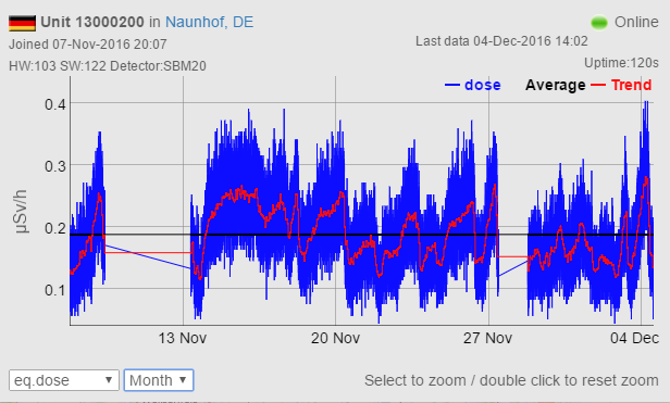
I thin anything in my unit is not okay. the cpm values seem to oscillate even the trend line. Look at the attachment. Other units in my region does not such a kind of oscillation. How can I investigate that?
https://www.uradmonitor.com/?open=13000200
 uRADMonitor
This oscillation is not normal.
I looked over the data and can advise you the following:
https://raw.githubusercontent.com/radhoo/uradmonitor_kit1/master/pcb/1.2.105/circuit/kit1_105_sch.png
1. change the compensation capacitor (C9)
2. change the geiger tube
Ateyo1. change the compensation capacitor (C9)
What do you mean exactly? Only replace with another one or another capacity?
uRADMonitorFirst keep the value in the schematics. Next try a bigger value like 100pF. Hope this helps, keep me posted.
AteyoA higher compensation capacitor (C9) seem to amplify this but not heal. So I also changed the tube. At first it seems to be better but it isnt away. I also changed the pwm frequency to 6500 to get a better duty.
uRADMonitorThe inverter voltage / duty data looks ok.
Please post a hires pic with your circuit so I can see the coil and the other components.
AteyoThe pic
Ateyo
 wanek
hello!
maybe i’m missing something, but what is the reason that you soldered the transistors in such a strange position?
do you still have the problem with that oscillation? i took a look now at your unit graph, and it seems normal to me…
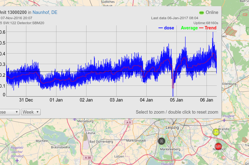
Ateyoset the graph to weekly and you see the oscillation. You also see a unit close to me with half the values. It’s a unit with the same components like me but another firmware an older one.
I don’t think that it is a issue from transistor soldering.
uRADMonitorNew hex sent by mail.