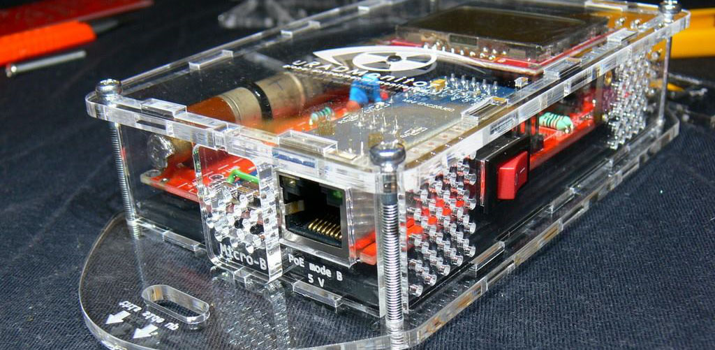
Open Source means collaborative work, joined effort leading to extraordinary things. Recently we saw how a talented maker from Oradea, Romania pushed his KIT1 #uradmonitor unit to the limit!

He used a lot of his personal time to build and document something better than the original. In the end he asked for nothing except to get access to the entire KIT1 source code so it can be improved further by the community of makers. We got the message and decided to act.
The server infrastructure
uRADMonitor is Big Data. Hundreds of detectors worldwide are collecting measurements every minute, and the server deals with millions of entries in its database every day. The database holding KIT1 data was designed for efficiency: only the minimum data goes in. One reason for open sourcing was to allow customising the KIT1 units with additional sensors. We had to adapt the server backend in this regards, and now there’s an expandable list of parameters that can be uploaded.
Then there’s the data accuracy which needs to be guaranteed to a reasonable degree by supervising and testing the hardware, something impossible with open, remote constructions. Making the server decide if the data is genuine or just some random useless bits was not an easy task.
Last but not least, here comes the security. Initially, open source can be a source of vulnerabilities of the exposed system. We had to make sure the new open communication protocol is safe to use. We’ve implemented API Authorisation for all data uploads generated by the Open Source KIT1 units. Go to the dashboard, and create an account if you don’t have one already. You’ll need to use the user-id and the user-key listed there with your new uRADMonitor KIT1. If you go for the stock firmware, then you won’t need them.
Please welcome the Open Source uRADMonitor KIT1
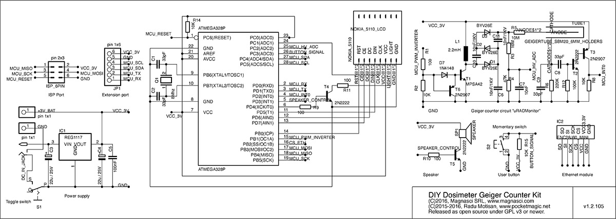
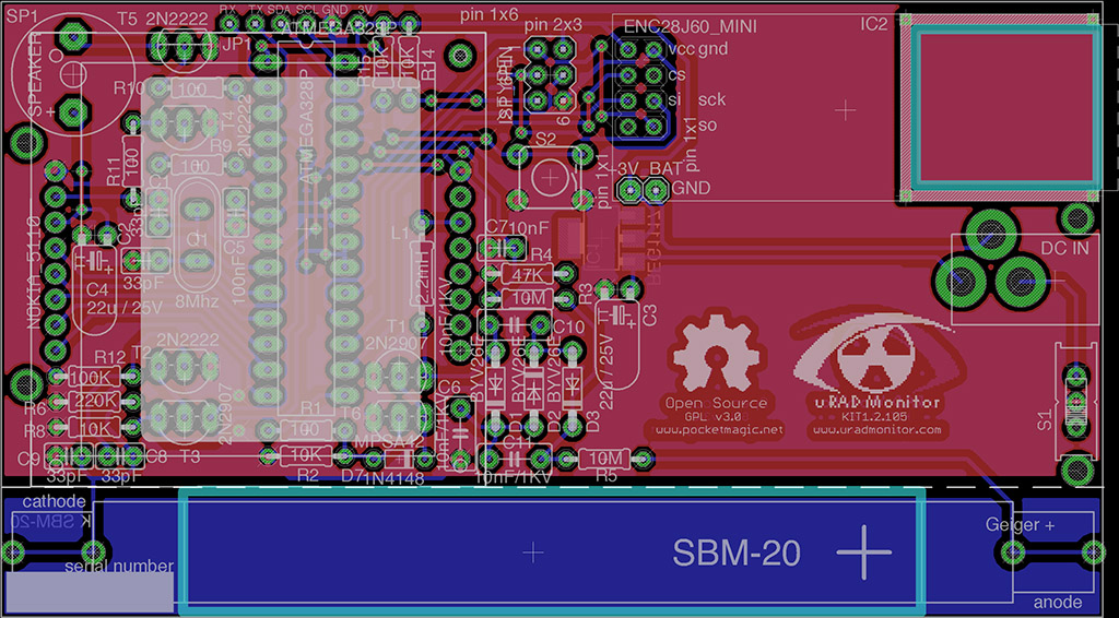
With so many changes on the server backend, we had to improve the KIT1 circuit and PCB. We tried to add many of the suggestions received on the forum. From now on however, feel free to fork the original Github repository and do whatever you like with this open design. The new version is KIT1.2.105, and you can see the first design images below:


The new design is more compact, so if you want to add a battery you’ll have more space. The arrangement of some components has been optimised and the regulator becomes the single SMD component on this otherwise exclusively through hole components PCB. As soon as we get the first of the new PCBs, we’ll add more pictures with them.
Using the KIT1.2
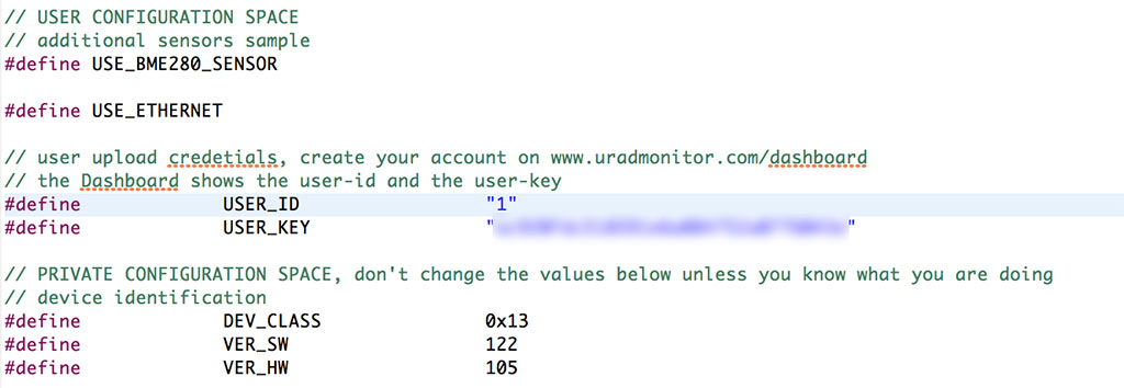
Once your KIT1.2 circuit is complete, download the firmware code from Github. In config.h add your user-id and user-key from the dashboard.

Compile the code, and write the HEX to your board, using a 6 PIN ISP connector. For the fuse settings, if you followed the original design, you’ll need to set the external 8MHz crystal, and make sure the EESAVE fusebit is set.
avrdude -p atmega328p -c usbasp -U lfuse:w:0xDC:m -U hfuse:w:0xD7:m
avrdude -p atmega328p -c usbasp -U flash:w:uradmonitor-KIT1-EXP.hex:i
Your unit will receive a device ID allocated dynamically by the server. If you want to use a BME280 sensor, there is code already in place. Just make sure the USE_BME280_SENSOR is set in the config file.
Adding more sensors
With the extension port that exposes I2C, UART and power, you have the possibility to add a large number of additional sensors. Add the sensor driver code, and do the sensor reading in app/data.cpp and app/data.h initSensors() and readSensorsSlow(). To send the data online, see the code file misc/expProtocol.h for parameter IDs and how they are used in uRADMonitor.cpp line 350. More parameter IDs will be added based on demand. All previous KIT1 hardware versions are compatible with the new firmware. For any questions and assistance, use the forum.
To compile the code, please use Eclipse and the AVR Crosspack plugin as well as the AVRDude software. For uploading the HEX code, you can use the versatile usbAsp programmer configured for 3.3V!
License
uRADMonitor KIT1 is released under GPL v3 or newer. Read the license terms here. For custom licensing, contact us.
Download PCB layout, Gerber files and firmware source code here.
Dear Radu,
I’ve took a look on the github files. I would like to know if is possible to access older releases, like for Kit 1 1.103.
Thank You
Yes, please see the folder named “old”.
I have created a fork of the .brd file that some folks may want to take a look at. I also have a few extra of these available. Just email me. My version cleans up the silkscreen and moves the sides away from some of the holes to avoid being charged for castellated holes by some board houses.
https://github.com/ukewarrior/uradmonitor_kit1
Excellent, thanks for sharing!
Hello,
at today there is any possibility to buy a KIT1 uRADMonitor?
Regards
Guglielmo
Italy
Does anyone know if a STS-5 tube will fit onto this new PCB without modification? It’s about 5mm longer than the SBM tube.
Yes, it fits just fine, a few guys that built the KIT1 used STS5, you’ll find a few pics on the forum. However I suggest it’s worth it to pay that little difference for a SBM20.
Good advice. thanks.
Sure. If you can post pics with your construction on the forum, there is competition with an A2 unit as the prize. You can win it just by posting pics with your KIT1. But time is limited, as the winner will be announced by the end of the week.
🙁 I won’t have my PCBs by then.
No worries, I will post pictures when done !
Can this new version work without the top layer?
Yes! You’ll need just 3-4 bridges, you can use some wire for that.
I will have to do some redesign of the board , I tried already two times etching the board but it’s tricky to solder with my 3$ soldering iron. Could I use some SMD components? Would there be problems if I would use SMD parts for the high voltage part?
You done great work Radu , thanks man for all the work you put in this 🙂
My pleasure, Adrian. Feel free to redesign it, no issues doing it with SMDs, see the model A pictures on http://www.facebook.com/uradmonitor to see its high voltage parts.
There was already a SMD redesign of the KIT1 done by Chris and Frederik, see it here: http://www.pocketmagic.net/diy-geiger-counter-kit-1-1/
Good luck, and send me a few pics when you finish it!
For the new Kit 1.2.105 board, you have moved to an smd 1117 regulator.
However, I not not find a 3.0V version of this regulator, unlike the old TO-220 package regulator on the prior Kit 1 board.
Do I need a 3.0 regulator or can I use a 3.3V?
If not, can someone please provide a source for a 3.0V 1117 regulator? Everything is find in a fixed voltage is 3.3V.
Thanks in advance for the help.
@ukewarrior sorry for the late reply. You can use a 3.3V regulator, it works even better.
Thank you for cool project, Radu. I built this device recently, and it’s working fine. Hovewer, I have few questions. First: On assembly schematic (red picture) transistors T1 and T6 are swapped. No voltage generation untill resoldered it properly (on principial schematic they are on correct positions). Is this mistake? Second: On LCD I see voltage 320V and duty cicle 80%. Also 3.3V regulator pretty hot (around 45c). Is this normal? If not, what I should check? Thank you!
Hi Keroron, thanks for the message, please send me a few pics with your build, I’d love to see it!
I remember there was a problem with the silkprint on T1/T6, but it’s not fixed on github. I didn’t produce new boards yet, so probably you were seeing the older pics.
Your second question requires more attention: the inverter should reach 380V, and the duty cycle should be lower (it’s not the duty the switching transistor sees, because there’s a blocking trasistor and the real duty is much lower, but still!). The critical components are (in order): the 2.2MH inductor and the MPSA42 transistor. Please try to find replacements for the inductor (different brand). Even try a 1MH inductor instead.
Keep me posted!
Thank you for support, Radhoo. I took some inductance from dead CFL lamp, and voltage raised to 400V, duty cycle was around 70%, though. I went to uradmonitor forum, and found one post, which suggested increase R3 and R4 in voltage measuring chain, to decrease load on HV side. I doubled resistance, and duty cycle dropped to 50%. So now everything seems to work fine.
https://puu.sh/yum4z/c903a44451.jpg