Forum Replies Created
-
AuthorPosts
-
R_A_Ghosh
ParticipantI used a small ac to ac 230v to 230v isolation transformer for mains isolation. Then used a full bridge diode doubler followed by a 68k 5w resistor in series with 200+200+100 V 5watt zener diodes to get 500V.
Extremely low noise than a dc dc converter that disturbed my previous setups ….
ParticipantWhat I did is to use an hvdc and two gm tubes with their separate anode resistors and cathode resistors and their respective compensation capacitor. Created two independent counter channels and finally added the counts per seconds.
I used two LND7807ParticipantAttached schematic is driven by 3V or two AAA batteries. Trying to interface a buzzer through a transistor switch from gm tube pulse but buzzer output is feeble.
Getting proper counts though.ParticipantI have also done the same, but no improvement. Core has cathode, braid has the 500V DC.
ParticipantParticipantRG6F capacitance is 53pF/meter so for 8.5 meters it is approx 450pF.
Find attached circuit. Please guide how to make improvements.
R anode is exact near GM tube as recommended.ParticipantHow many for 8.5 meters cable ?
ParticipantSo I finally did that. Used cathode wiring and put 82pF compensation capacitor across R2 and it worked like magic. Got good calibration and now basic instrument working. Rest will be done in due time.
ParticipantOne more thing is that I have the both biasing resistors on the PCB board and the gm tube is then connected by a foot long wire and kept far. If as per suggested I can take the anode resistor to GM tube assembly close to the GM tube anode and from return wire of cathode i take cathode wiring connection as recommended by you and hence using a compensating capacitor on board, then can the problem be mitigated ?
I have R anode=3.3M
R drop at cathode =330K
Capacitance of tube = 8pF
then formula 3.3Mx8pF=Ccx330K
Cc =80pF
So if i do such that I change the wiring to cathode signal type and use 80pF compensation capacitor.ParticipantThe power supply I am using has capacity of 500V, 1mA. I am using 100X probe to measure HVDC. As per LND7807 datasheet and some emails sent to me by LND support for 10mR/hr it consumes no more than 10uA current…attaching graph here sent to me by LND support.
I have a switching frequency of 9KHz of the DC to HVDC supply. The link to make one is here HVDC Power supplyAttachments:
ParticipantThough my HVDC power supply is clean and well filtered, I did not observe any false count on my monitor. I have to impose the system on high radiation and see if it still works or gets GM tube noise again.
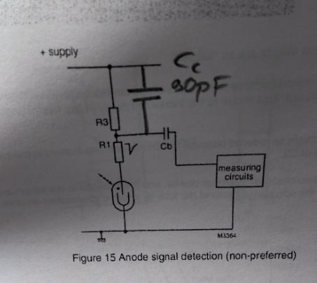
My problem was that I had simple wiring earlier and everything was fine until 3mR/hr or 450 counts/s, over that it worked well for few minutes and then suddenly a high fixed false pulse count of 4000/s started to come. It fell back to normal when radiation was reduced. I have proper data upto 3mR/hr. I want to measure upto 10mR/hr but the GM tube noise is causing issues. The noise is not from HVDC power supply for sure.ParticipantI am using anode signal model without the compensation capacitor, so after 3mR /he I am getting noise in GM reading and false high counts, why is it happening with lnd7807 tube? .as a solution I may need compensation capacitor…Is this how shall I connect compensation capacitor to avoid noise (find attached)?
I am using 3.3M R1 as anode resistor, 330k as divider R3
I am not using cathode signal model as your kit….Attachments:
-
AuthorPosts