- This topic has 10 replies, 3 voices, and was last updated 7 years, 7 months ago by
uRADMonitor.
-
AuthorPosts
-
October 24, 2018 at 4:28 pm #6223
R_A_Ghosh
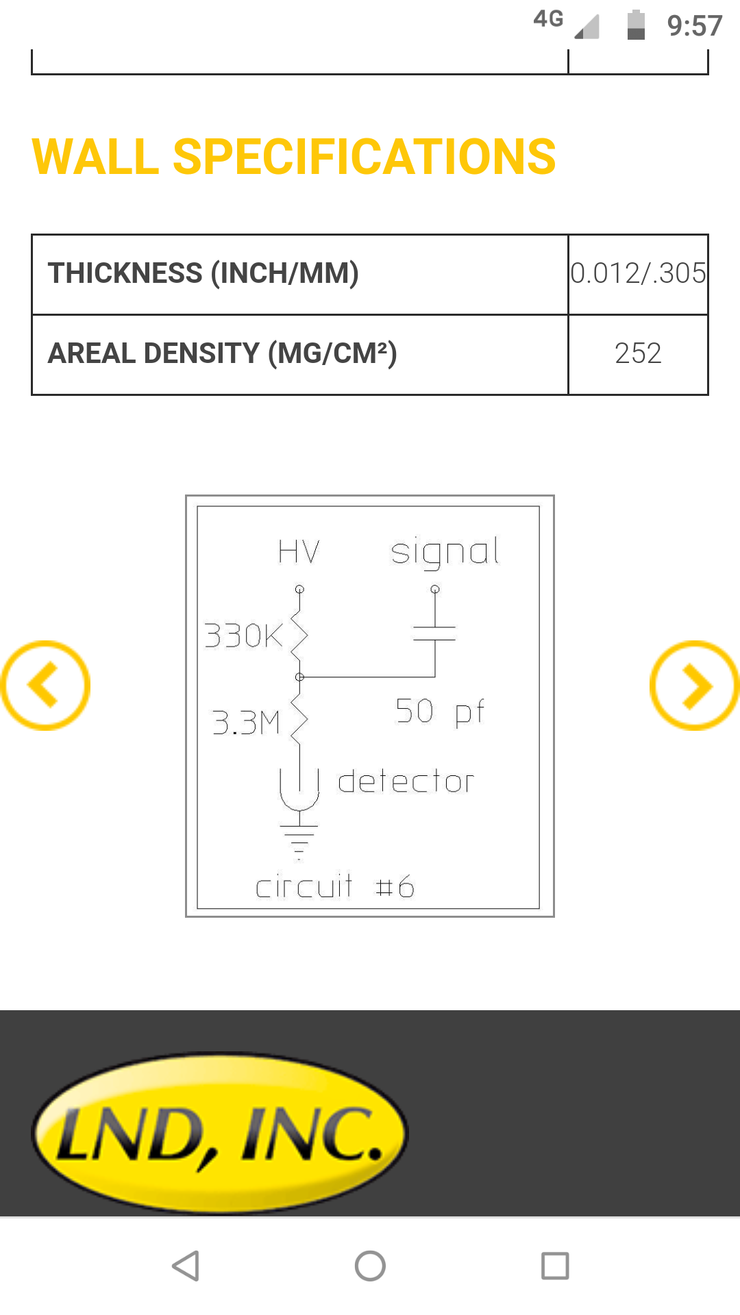
ParticipantI am making a uRadmonitor variant using LND7807 GM tube from LND. I am using anode signal biasing as per 7807 datasheet. R2 is 330k ohm, R1 anode resistor os 3.3M ohm. How to calculate and connect compensation capacitor in anode signal connection mode. Signal dc blocking capacitor is 47pF
Basic wiring is as below+500V—–R2—–R1—–GM tube anode
|
C1
GM tube cathode is connected to ground.I am getting spurious noise at high radiation rates. Though solution are there for cathode signal connection method. But I am using anode connection. Please guide.
Attachments:
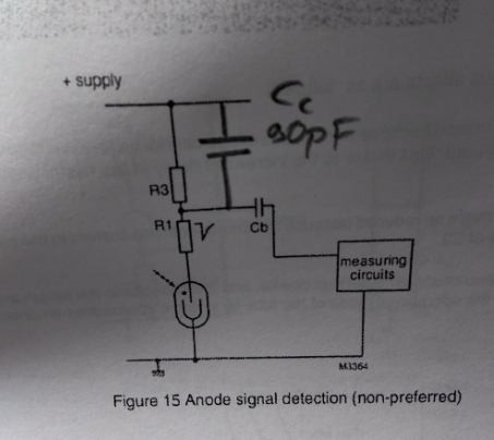
October 26, 2018 at 8:32 pm #6259ParticipantI am using anode signal model without the compensation capacitor, so after 3mR /he I am getting noise in GM reading and false high counts, why is it happening with lnd7807 tube? .as a solution I may need compensation capacitor…Is this how shall I connect compensation capacitor to avoid noise (find attached)?
I am using 3.3M R1 as anode resistor, 330k as divider R3
I am not using cathode signal model as your kit….Attachments:
October 27, 2018 at 9:26 am #6262ParticipantThough my HVDC power supply is clean and well filtered, I did not observe any false count on my monitor. I have to impose the system on high radiation and see if it still works or gets GM tube noise again.
My problem was that I had simple wiring earlier and everything was fine until 3mR/hr or 450 counts/s, over that it worked well for few minutes and then suddenly a high fixed false pulse count of 4000/s started to come. It fell back to normal when radiation was reduced. I have proper data upto 3mR/hr. I want to measure upto 10mR/hr but the GM tube noise is causing issues. The noise is not from HVDC power supply for sure.October 27, 2018 at 10:12 am #6264ParticipantThe power supply I am using has capacity of 500V, 1mA. I am using 100X probe to measure HVDC. As per LND7807 datasheet and some emails sent to me by LND support for 10mR/hr it consumes no more than 10uA current…attaching graph here sent to me by LND support.
I have a switching frequency of 9KHz of the DC to HVDC supply. The link to make one is here HVDC Power supplyAttachments:
October 27, 2018 at 10:20 am #6266ParticipantOne more thing is that I have the both biasing resistors on the PCB board and the gm tube is then connected by a foot long wire and kept far. If as per suggested I can take the anode resistor to GM tube assembly close to the GM tube anode and from return wire of cathode i take cathode wiring connection as recommended by you and hence using a compensating capacitor on board, then can the problem be mitigated ?
I have R anode=3.3M
R drop at cathode =330K
Capacitance of tube = 8pF
then formula 3.3Mx8pF=Ccx330K
Cc =80pF
So if i do such that I change the wiring to cathode signal type and use 80pF compensation capacitor.December 3, 2018 at 6:51 pm #6302ParticipantSo I finally did that. Used cathode wiring and put 82pF compensation capacitor across R2 and it worked like magic. Got good calibration and now basic instrument working. Rest will be done in due time.
December 4, 2018 at 10:12 pm #6303uRADMonitor
Keymaster@r_a_ghosh, would you post a few pics too?
-
AuthorPosts
- You must be logged in to reply to this topic.