Home › Forum › Hardware › KIT1 Feedback › Reply To: KIT1 Feedback
 ecloud
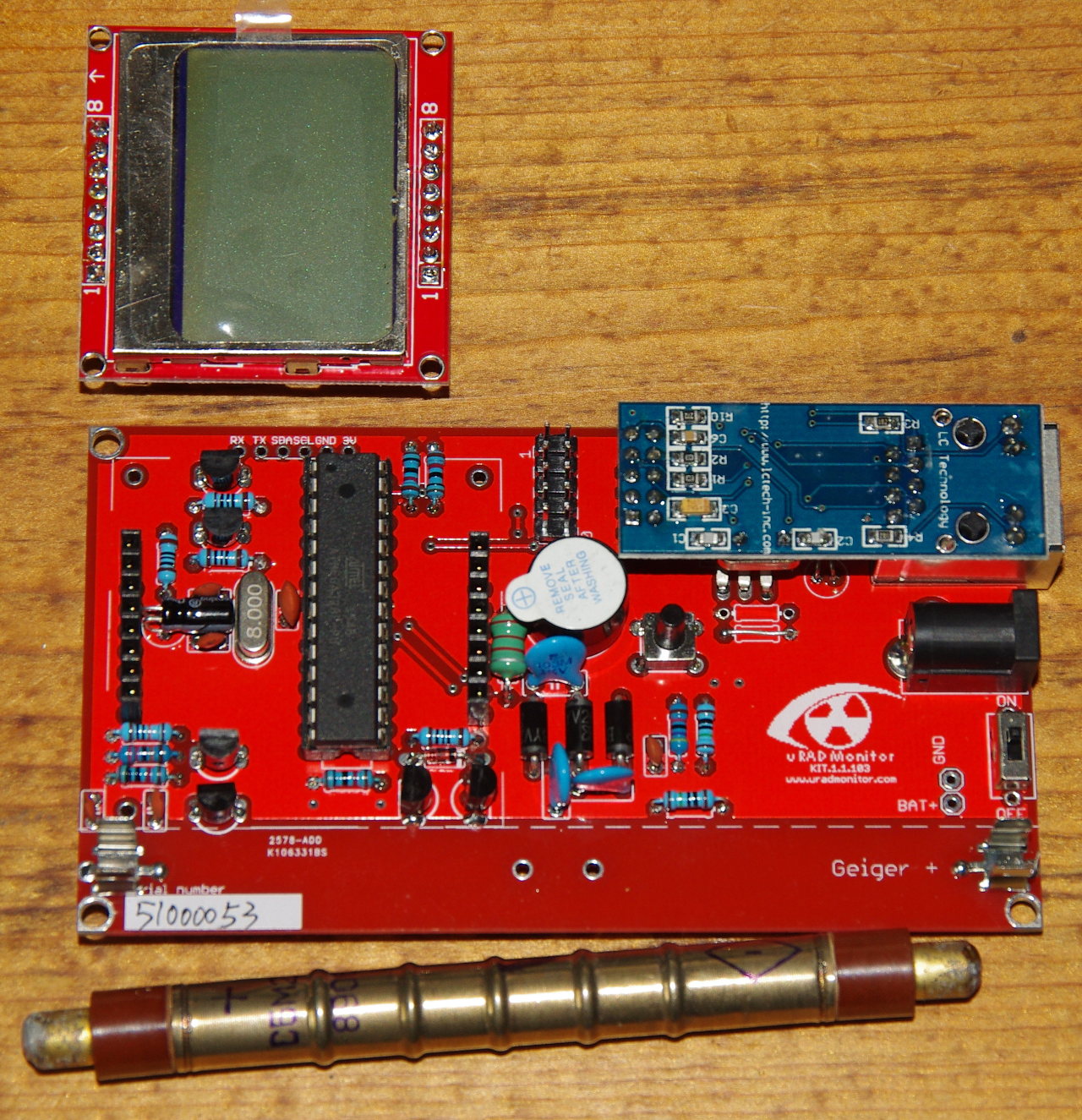
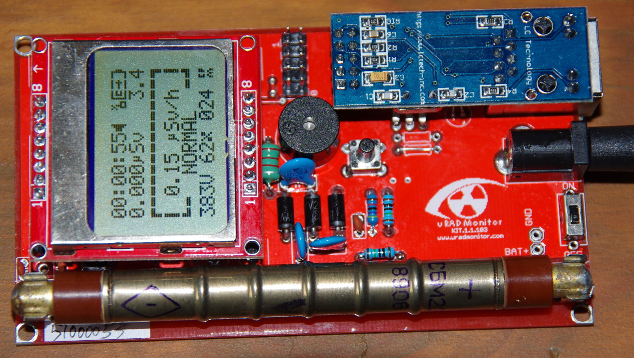
I also managed to bend the legs of the fuseholder such that it’s possible to solder both ends, like Robert described. They strike me as quite a flimsy holder for the tube; but on the other hand, they are also too close to the mounting holes. So since they are so flimsy, it wasn’t too hard to bend them over a bit crooked, to make it possible to bolt the board into a case I designed, which is here: http://www.thingiverse.com/thing:1644939 The case includes struts which, if you have bent over the fuseholders the same way I did, will help hold the tube in position, so that it doesn’t fall out.
I’d suggest using sturdier fuseholders, but also making the board just a little bigger, to get those mounting holes away from the tube. Also, it would be nice to have holes on all 4 corners, not just 3. Moving the ethernet module over might make it possible.
I will leave it plugged into the network at home most of the time I guess, but designed the case so that I can slip a Nokia BP-4L battery into the back, for checking other places around town, etc. 3.8V is too high, so I used a diode to drop it down around 3.2-3.3V. At least this way I didn’t need to bulk it up to make space for a pair of AA’s. But using this type of battery is fiddly. It’s nice that the battery can clamp onto the battery contacts in the phone, instead of needing spring-loaded contacts. But you need something resembling the contacts in the phone. I used diode legs as battery contacts. Maybe I should make a PCB which can hold the actual surface-mount Nokia battery contacts that can be found on ebay, and have the board double as the inside plane of the battery holder, and slot into the case somehow. It could have a battery charging controller too. For now I will need to use a separate charger.
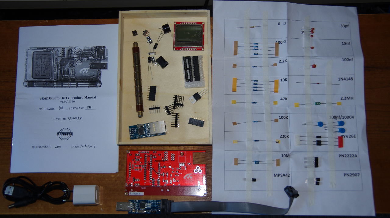
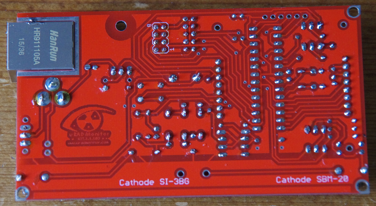
Attached pics are simply the board during assembly. Thingiverse has more pics of the case design.