Home › Forum › Hardware › DIY KIT1 assembly roundup/lessons: transistors swapped, high-resistance inductor
- This topic has 18 replies, 4 voices, and was last updated 7 years, 5 months ago by
a3an0.
-
AuthorPosts
-
January 2, 2017 at 9:50 am #3962
a3an0
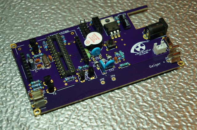
ParticipantHere is a quick roundup of the issues I ran into when assembling the DIY KIT1:

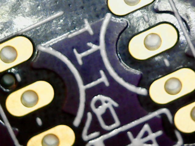
Transistors T1, T6 swapped
At first, the voltage produced was very low: 16-18V. It turned out I had swapped the two transistors T1 and T6 due to unclear markings at the PCB (version 1.0.102): the markings are actually closer to the opposite transistor, so check carefully with this layout to make sure these transistors are placed at the correct position.

Inductor DC resistance too high
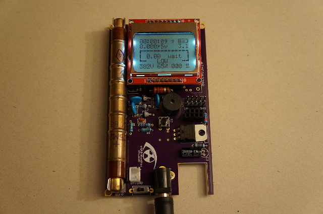
Swapping the transistors lifted the high voltage to 290V, still 100V short to get the tube working. It turned out that the inductor was too slow: it’s DC resistance was 23 Ohm (a light green one sourced from China/AliExpress). After replacing it with an 9 Ohm inductor (sourced from DigiKey), everything was running smoothly. The larger inductor, however, has not enough room to be mounted on the board nicely.

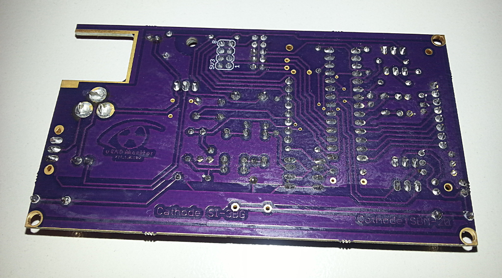
Final (non-critical) issue I had was with the boards: after cleaning the board (manufactured by OSH Park) with IPA, the purple top layer was severely damaged. I had similar problems with other boards purchased from them, so I will not be using their service any longer.
January 2, 2017 at 10:21 am #3966ParticipantA picture of the back side of the board: it turned out that cleaning with IPA “chemically burnt” the board.
I had similar problems with other boards from OSH Park, so beware/test before assembling, or use an alternative manufacturer before soldering everything together!Attachments:
January 3, 2017 at 9:34 am #3969uRADMonitor
KeymasterThanks for this excellent feedback. For those that need it, please have a look on the new version as well: https://github.com/radhoo/uradmonitor_kit1 silkscreen layer should be carefully aligned now.
July 23, 2018 at 1:03 am #5968sam
ParticipantHello Radu and a3an0,
I am facing similar issues with the 1.2 kit. I had the PCB printed by PCBCART and parted the BOM myself.
Using mostly no-name Chinese components (I have since learned my lesson about component quality…) I had low voltage across the tube (around the 200V arena).
I first attempted to fix this by replacing the MPSA42 (with this https://www.mouser.com/ProductDetail/610-MPSA42). The voltages improved to around 300-340V but still not getting the desired 380V.
Next I considered the inductor, my no-name one turned out to have 22 ohm resistance. I replaced it with one having 4.5 ohm resistance (https://www.mouser.com/ProductDetail/815-AIAP02222K). The tube could finally reached 380v however there is a lot of instability and duty cycle is high.
I fear that the readings are inaccurate because after each few cycles/readings the voltage fluctuates, bouncing between 340-400V. The duty cycle starts out around 70% when first turned on, then after running for a few minutes climbs and stays at 90%.
Lastly I tried replacing the 1KV caps (with these https://www.mouser.com/ProductDetail/81-RDER73A103K2K1H3B), and the BYV26E diodes (with these (https://www.mouser.com/ProductDetail/78-BYV26E). There was no improvement.
Can you see anything wrong with the specs of the new components I have installed? Is it possible that the inductor now has too low of a resistance (4.5)? I have checked my solder joints and they appear to be fine. I have 4 more PCBs that I can try a fresh build with– but I would like to figure out why this one isn’t stable.
Any advice you can provide would be great, thank you!
July 23, 2018 at 3:11 pm #5972ParticipantWolferl, thank you that is a good point
I found that out early on that measuring with a DMM showed a wildy inaccurate reading for the tube
The voltages described in my post above are based on what is reported by the uRADmonitor display
July 24, 2018 at 10:21 pm #5981KeymasterHi @Sam,
Indeed the MPSA42 and the 2.2mH inductor are critical in terms of quality. But I wouldn’t blame the Chinese channels. After all, everything is made there, just be careful when you select the goods and the provider.
Please increase R1 from 100 to 1K and R2 to 47K.
What duty cycle does this give you? NExt try to change the frequency, in inverter.h, in the code. Try to reduce it by 1kHz until down to 10kHz. What do you see?
Here’s a nice chart I made from a similar circuit: https://www.pocketmagic.net/global-radiation-monitoring-network/#131005
July 25, 2018 at 3:26 pm #5982ParticipantThank you @radhoo,
That’s right– not to criticize Chinese channels but it goes to show that buying the cheapest unbranded/bulk components may not save you time and money in the end
I will experiment with those resistor values and frequencies. This gives me the direction I need to continue debugging.
I will report back with my findings. Thanks again!
July 25, 2018 at 5:22 pm #5983KeymasterSounds good, waiting for your update. Thanks!
August 5, 2018 at 10:22 pm #5985ParticipantHi Radu,
I played around with the R1 and R2 values (by soldering in potentiometers) and did not find that they made much of a difference with higher values– in terms of voltage stabilization or reducing the duty cycle.
However, I did find that lowering the inductor frequency would drop the duty cycle 10% or more with each 1khz reduction.
At 7-8khz the duty cycle is solid at 50%. This seems really low– do you think this would affect accuracy or is the khz primarily a concern of audible noise?
It seems I have two separate problems, the high duty cycle and the wild voltage fluctuations.
The duty cycle was fixed by lowering the freq. Then I found that the wild voltage fluctuations went away by attaching the ENC28J60. Without the ethernet module attached, there are 40-50 voltage swings. With the module attached it settles to deviations of 10 volts but with most of the time resting at a steady 380v
I have watched the 3.3v rail and it stays clean, no noise. I tested powering from batteries, DC jack, rigol bench power supply, and USBasp programmer set to 3v. I believe that the voltage regulator is fine as this was tested with the DC jack.
When it was running steady at 380V / 50% duty, I logged data for about an hour and noticed waves of brief high CPM readings (low to normal most of the time, then 5-10 seconds of high readings). I question their accuracy however, there is nothing around that should be producing high radiation. Do you know if the tubes are susceptible to RF interference?
I will continue to investigate. It may just be this first build is haunted. I will begin constructing another one for comparison
August 6, 2018 at 8:08 am #5986KeymasterHi Sam, for lowering the frequency there are no issues other than entering the audible spectrum. I can confirm your results here.
Please note that the voltage regulator algorithm thinks that with increased duty cycle there comes increased voltage. If you’re seeing serious swings you might need to change it.
The tubes well shielded by design in regards to RF, but the counter circuit (PCB traces, components) are not. But I don’t think the high voltage inverter is of concern here.
Having two units is definitely the way to go here, and try to get the Ethernet running so you can automate the process.
Good luck!
RaduAugust 6, 2018 at 2:33 pm #5988ParticipantThank you both for your help!
I put this board to a lot of stress with soldering and desoldering, but it has been a good learning experience. I will assemble a new board and should get better results, as well as provide me some more performance information to help me understand and compare the two units.
On a side note, another thing I noticed is that putting a single finger on the geiger tube would trigger danger CPM readings– is that normal behavior? I found that I did not have to ‘short’ the tube to another part of the board for this to happen. I can see how for hand-held use it would be critical to have some sort of enclosure
Thanks again
September 4, 2018 at 4:22 am #6008ParticipantHello again!
I have gone through the assembly process a second time. I have a new shiny unit– I am getting a solid 380V but the duty seems unusually low around 18% (at the default 13khz inverter configuration). Should the goal be to have around 50% duty for correct operation, or is anything less acceptable?
However there is now a new problem, the microchip appears to be running very slow. The device is slow to boot, and the screen is slow to change, it takes several seconds to update the timer for example. I have tried another microchip and it has the same issue. I am wondering if the 8mhz crystal is bad or one of the capacitors in that crystal circuit.
I will continue tinkering.
October 3, 2018 at 9:15 pm #6087KeymasterOctober 8, 2018 at 6:02 am #6112ParticipantHello, thank you for your replies and sorry for my late responses
Following your suggestion I did find that my oscillator circuit wasn’t functioning because of my fuse settings.
I now have the circuit oscillating but my device is rebooting frequently (on its own, without shorting or touching it)
It may be possible I am still using the wrong fuses. Are these the correct settings?:
LOW: 0xDC
HIGH: 0xD7
EXTENDED: 0x07 -
AuthorPosts
- You must be logged in to reply to this topic.