- This topic has 15 replies, 5 voices, and was last updated 5 years, 11 months ago by
Wolferl.
-
AuthorPosts
-
June 18, 2016 at 1:22 pm #3044
tuxik
ParticipantHello,
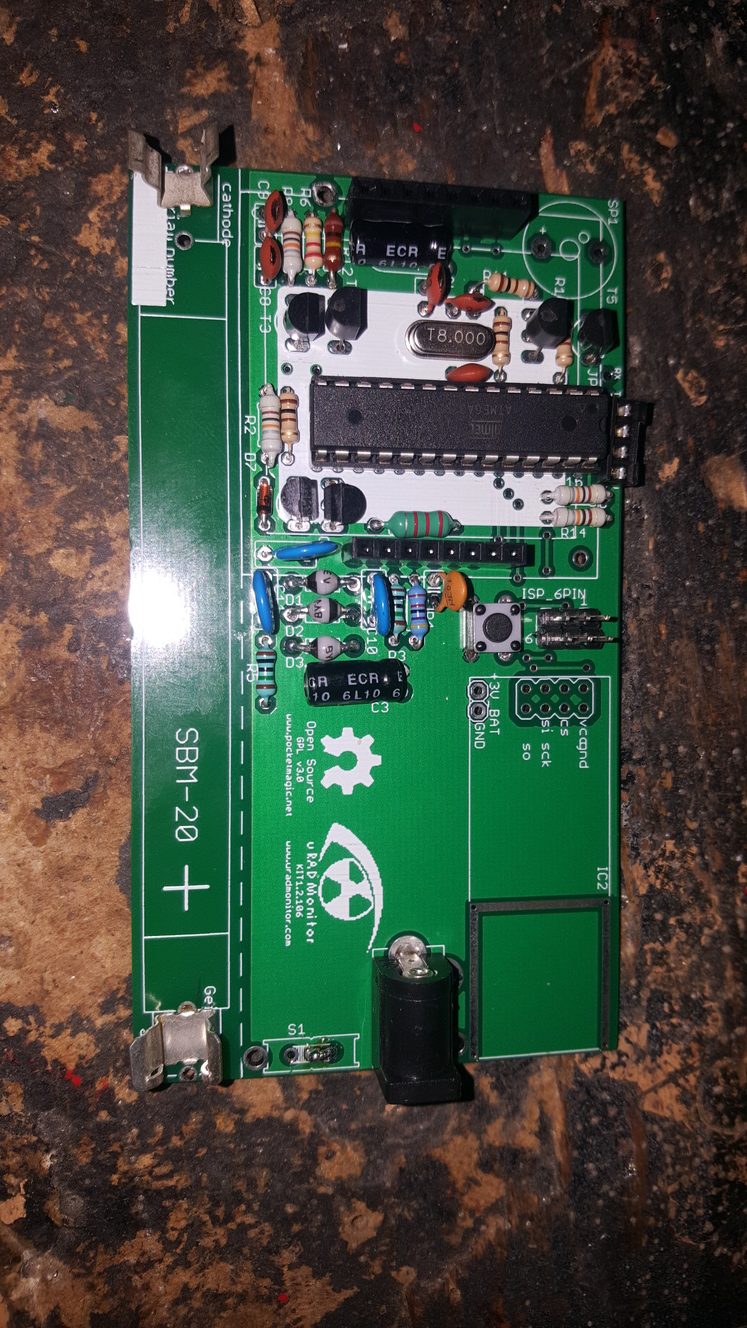
recently i soldered unit on custom PCB and i am not able to tune voltage at GM tube – there is only 250-270V. I changed MPSA42, inductor, but problem is still here 🙁 On first stage of voltage pump is 127V (at second diode). Any idea where problem may be ?
Thanks
-
This topic was modified 10 years ago by
uRADMonitor.
-
This topic was modified 10 years ago by
June 18, 2016 at 1:23 pm #3045June 19, 2016 at 7:33 pm #3047uRADMonitor
KeymasterI’ve seen this before, and the problem was related to the inductor. Try getting 2.2mH inductors from a different source, or ,as a quick dirty hack, put two 2.2mH inductors of the kind you have now in parallel.
We might get over this by changing the frequency the inverter operates at – drop me a mail so I can send you a test firmware that uses a lower frequency (that might get noisy).
June 20, 2016 at 9:04 am #3053KeymasterI also sent you by mail versions of the firmware configured for lower inverter frequency (down to 6.5KHz). Please test them and let me know if it helps.
October 16, 2016 at 8:23 am #3679jon
ParticipantWe tested a lot of transistors from different sources. The best Voltage/Duty ratio, we got it with the transistor (T2)
http://www.reichelt.de/BF-299/3/index.html?ACTION=3&LA=446&ARTICLE=5464&artnr=BF+299&SEARCH=bf299
BF 299 :: Transistor HF NPN TO-92 300V 0,1A 0,625W
and
http://www.reichelt.de/L-XHBCC-2-2M/3/index.html?ACTION=3&LA=446&ARTICLE=138556&artnr=L-XHBCC+2%2C2M&SEARCH=2.2mh
L-XHBCC 2,2M :: Festinduktivität, axial, XHBCC, Ferrit, 2,2 mHbest regards.
October 16, 2016 at 3:39 pm #3682KeymasterPerfect, thanks for the update!
November 19, 2019 at 7:46 pm #6866ParticipantHello all,
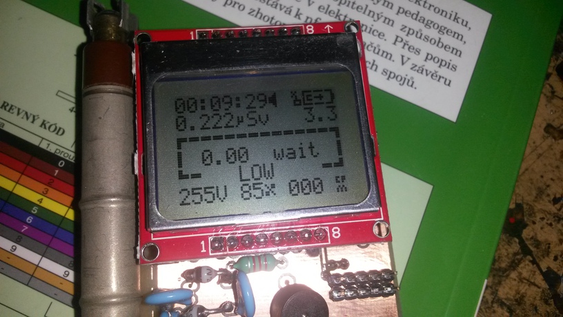
i have build another uradmonitor, but problem with low voltage is here again (same as on first piece 3 years ago) – and voltage is extremely low.
I lowered down frequency of oscillator, but no change occures.
Some ideas ?
Thanks,
November 22, 2019 at 8:08 pm #6879ParticipantSorry, my failure 🙂 Two of transistors was misplaced, everything is now ok
June 21, 2020 at 11:16 am #28406Outsider
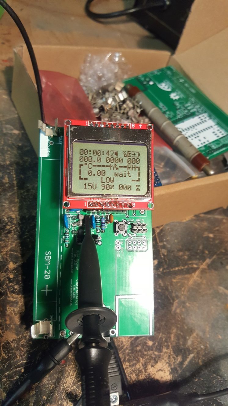
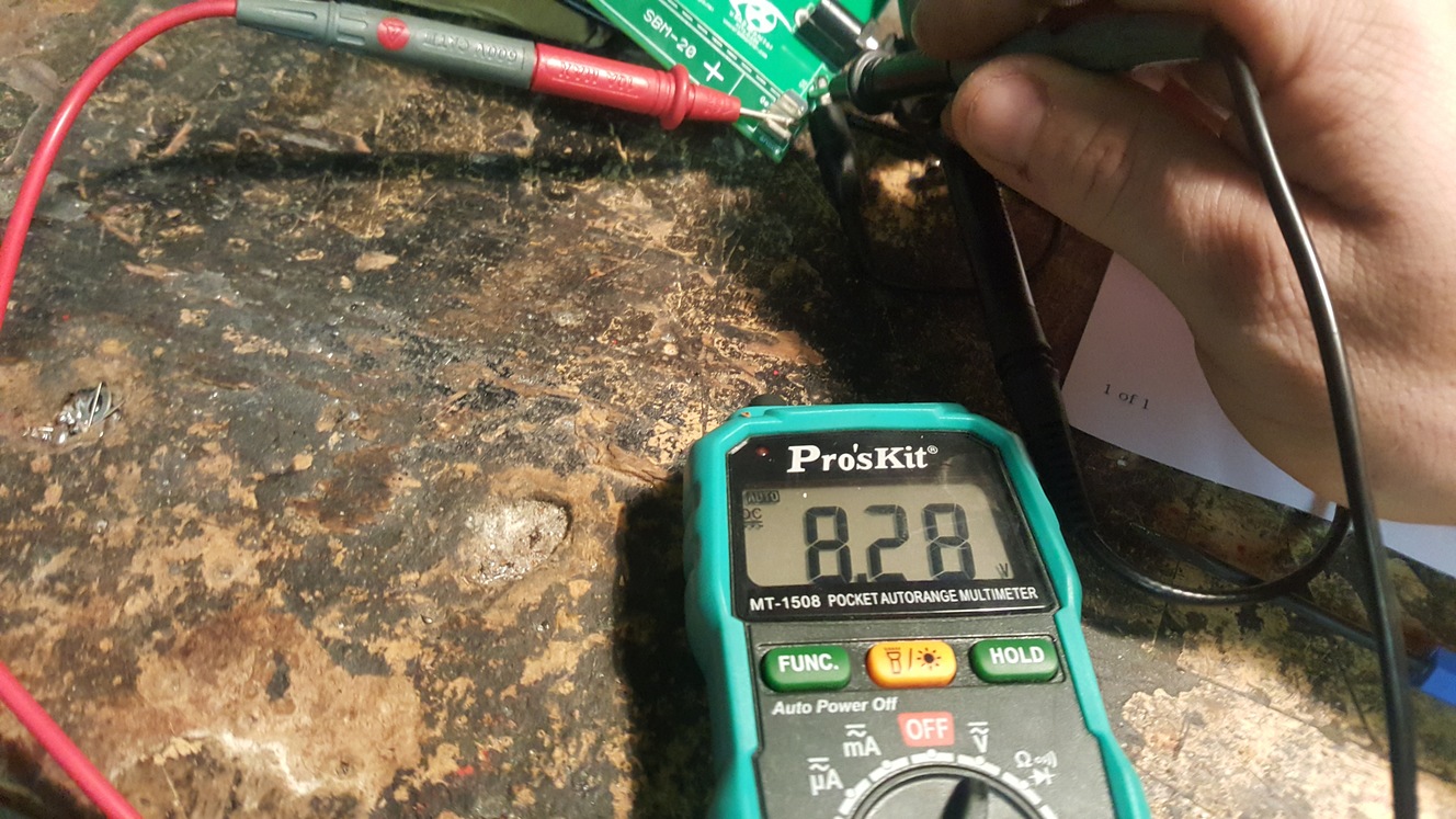
ParticipantTuxik, could you please elaborate on the problem? Ițm having the same situation here (15V on LCD, 8V measured across the tube).
Thank you!June 25, 2020 at 11:26 am #28419Wolferl
ModeratorHi Outsider,
What do you mean with “15V on the LCD”? That seems totally wrong. Nowhere on the LCD module should be a voltage greater than 5 volts!
Cheers,
WolferlJune 25, 2020 at 3:44 pm #28420ParticipantHi Wolferl!
My mistake… I meant the internal voltage measurement is 15V, as it is shown on the LCD.
The LCD is powered at 3V (2xAA batteries).
I have replaced the small axial inductance (2.2 mH, 32 ohms) with a larger, ferrite-core one (2.2 mH, 3 ohms),
but the voltage remained the same.July 25, 2020 at 11:12 am #28463ParticipantWhile I’m waiting for help for compiling/modifying the firmware for my STS-1 tube (practically identical to the SI1G already defined in the code), I’m troubleshooting the high-voltage stage. I’m using firmware made to work with the SBM-20 tube while I have a STS-1 version, but I don’t think that is the reason for having such a low voltage – 15V on the tube!
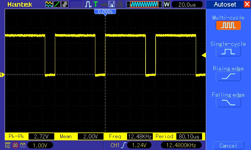
I took some measurements with the oscilloscope. Could it be the MPSA42 transistor? Or the 2N2907 transistor?
The coil is a quality 2.2 mH, very low resistance, not the green version that looked like a resistor.
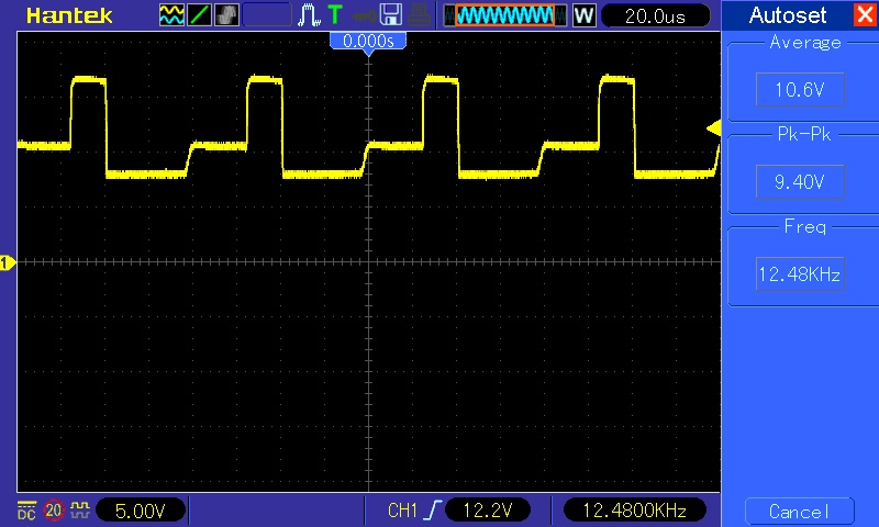
Any ideas? Can someone measure same test points on their units?July 25, 2020 at 1:30 pm #28468ModeratorHi,
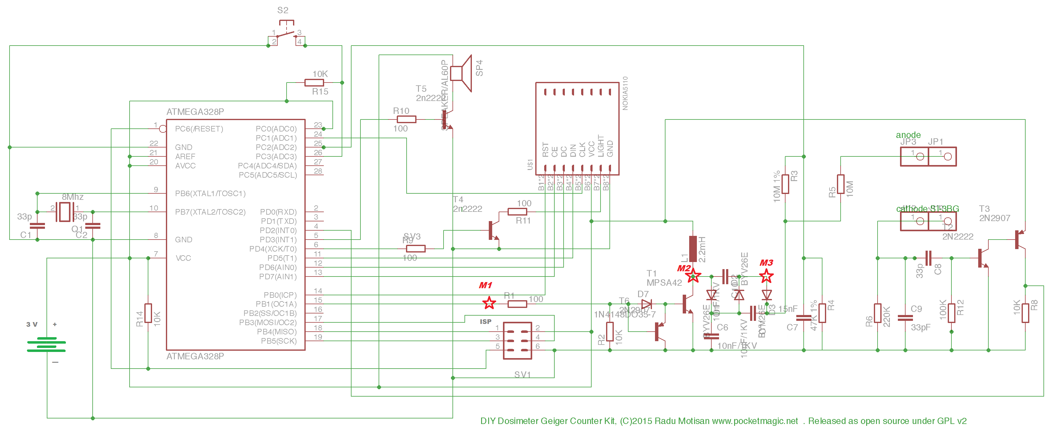
You can’t measure at M3 directly. It has a very high impedance, a multimeter or an oscilloscope probe loads the voltage down so much. You would need a voltmeter with a input resistance of 100 MOhms at least to get meaningful results. And you’d need to measure not at M3 (anode) but on the cathode of the diode. You can instead use scope or multimeter across R4 and multiply the reading by 214 to get the real high voltage value.
That M1 measurement looks weird. It has only 2,7 volts peak-peak. That should be more like 3.3 to 3.6 volts. Frequency looks good.
What you can try: with the KIT1 turned off, check the resistance of the connection R3 to R3 (the 2 10Mohms resistors) to ground. It must read 10 MOhms.I hope I can find some time for your firmware tomorrow.
Cheers,
WolferlJuly 25, 2020 at 1:48 pm #28469ParticipantThe low 15V tube voltage is also displayed on-screen (KIT1 screen, not multimeter).
I have measured R3 to ground: 8.5 Mohm. R3+R5 to ground: 17.2 Mohm (with the tube in circuit).
I suppose M1 has only 2.7V because I use 2xAA batteries to power the kit.July 28, 2020 at 3:50 pm #28472ModeratorHi folks,
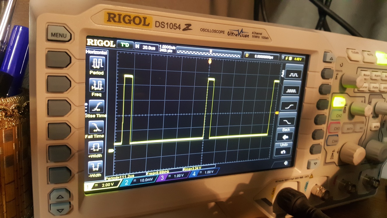
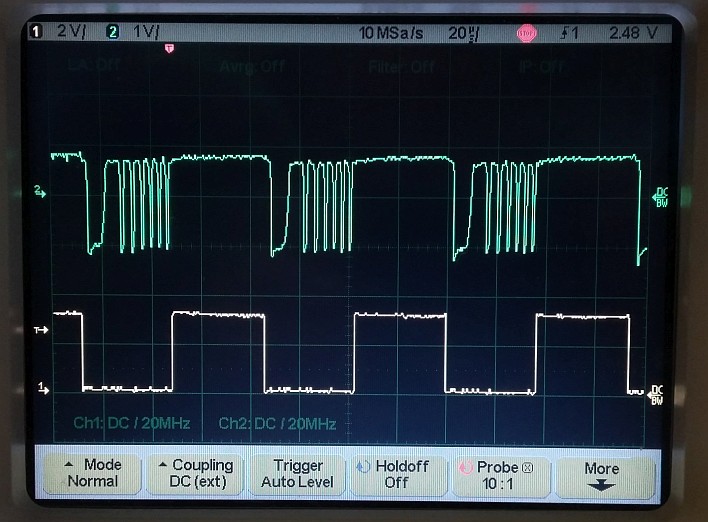
Since I had my KIT1 apart, I took some measurements with the scope for comparison.
The yellow curve (lower trace, 2 volts per division vertical, 20µs per division horizontal) is the PWM output of the MCU. We see it is running at about 50% duty cycle, which is good.
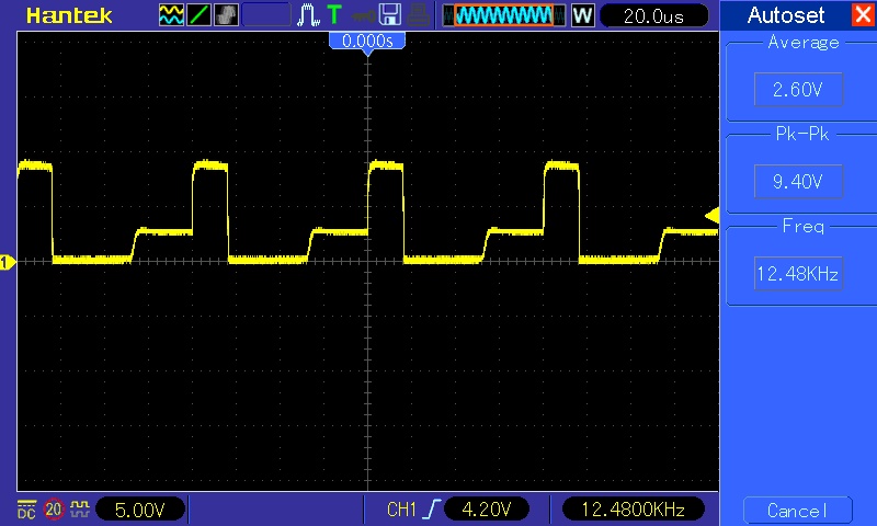
The green curve (upper trace, 1 volt per division) is probed at the cathode of diode D7. We see some ringing when the current in the inductor is turned off.
That’s normal. HV is 380 volts (displayed).
If you have no ringing, you have no high voltage spikes. Loading the collector of the MPSA42 with a 10Mohms probe completely kills the HV (duty goes up to 90% which is the maximum).
If you probe there, be careful, there are 200 volts peaks present! Do not kill your scope 🙂I have the original parts for transistors and inductors as the kit came from factory.
The only thing I modified are:
R3 is 47Mohms instead of 10MOhms
R4 is 220kohms instead of 47kohms
That yields the same divider ration of 213.
These modifications creates less load on the high voltage and reduced current consumption dramatically, plus reduces stress on the parts.Cheers,
WolferlAttachments:
-
This topic was modified 10 years ago by
-
AuthorPosts
- You must be logged in to reply to this topic.