Home › Forum › Hardware › DIY KIT1 v102 – Unit voltage on GM tube is too low › Reply To: DIY KIT1 v102 – Unit voltage on GM tube is too low
 Wolferl
Hi folks,
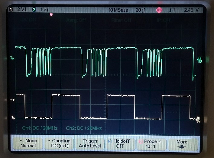
Since I had my KIT1 apart, I took some measurements with the scope for comparison.
The yellow curve (lower trace, 2 volts per division vertical, 20µs per division horizontal) is the PWM output of the MCU. We see it is running at about 50% duty cycle, which is good.
The green curve (upper trace, 1 volt per division) is probed at the cathode of diode D7. We see some ringing when the current in the inductor is turned off.
That’s normal. HV is 380 volts (displayed).
If you have no ringing, you have no high voltage spikes. Loading the collector of the MPSA42 with a 10Mohms probe completely kills the HV (duty goes up to 90% which is the maximum).
If you probe there, be careful, there are 200 volts peaks present! Do not kill your scope 🙂
I have the original parts for transistors and inductors as the kit came from factory.
The only thing I modified are:
R3 is 47Mohms instead of 10MOhms
R4 is 220kohms instead of 47kohms
That yields the same divider ration of 213.
These modifications creates less load on the high voltage and reduced current consumption dramatically, plus reduces stress on the parts.
Cheers,
Wolferl